System and method of light spot position and color detection

a technology applied in the field of light spot position and color detection system and method, can solve problems such as reducing accuracy

Inactive Publication Date: 2006-04-04
NAT RES COUNCIL OF CANADA +1
View PDF21 Cites 47 Cited by
  • Summary
  • Abstract
  • Description
  • Claims
  • Application Information

AI Technical Summary

Problems solved by technology

However, accuracy is reduced when spurious light is

Method used


Image

  • System and method of light spot position and color detection
  • System and method of light spot position and color detection
  • System and method of light spot position and color detection

Examples


Embodiment Construction

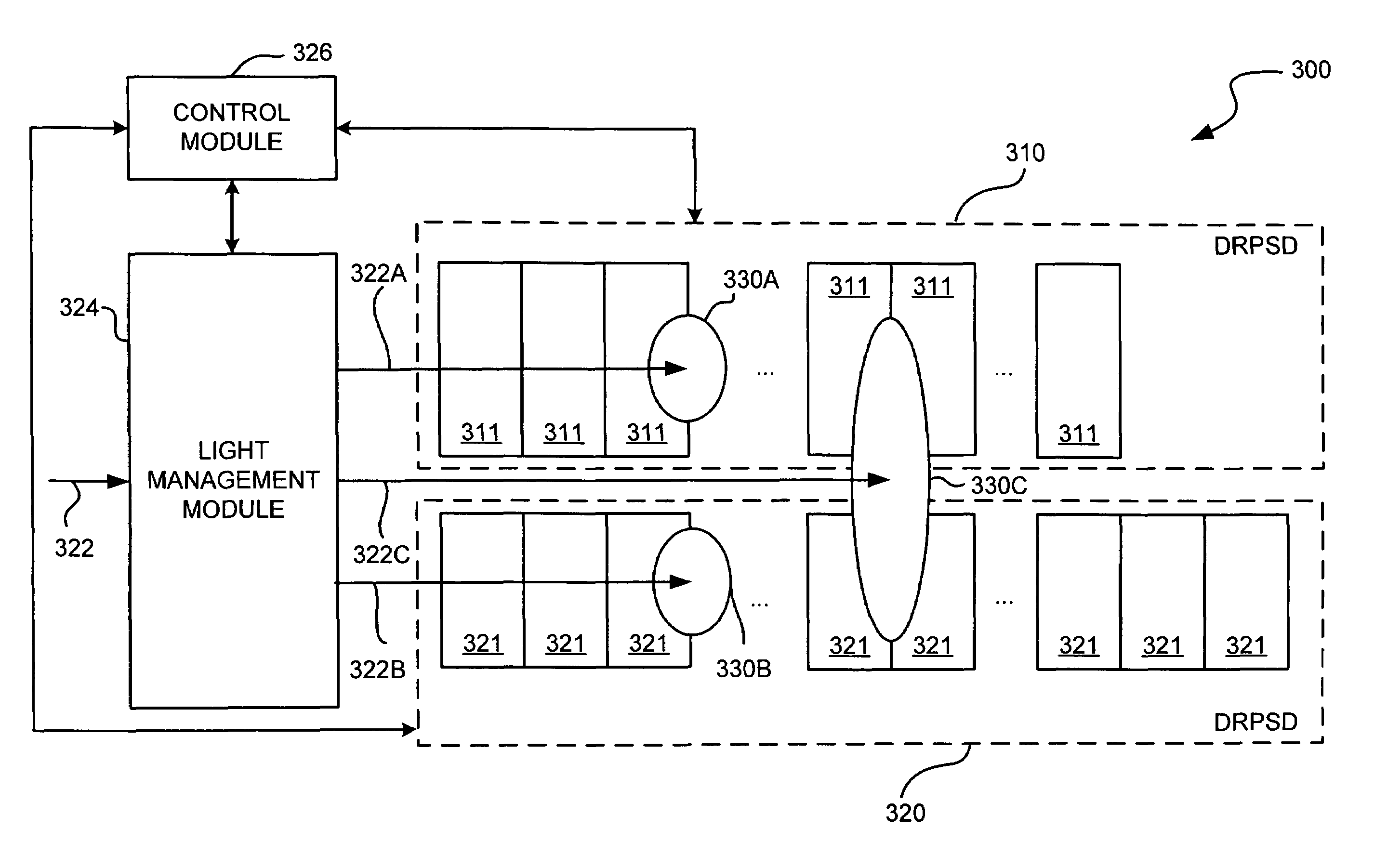
[0022]By way of background, continuous response position sensitive detectors (CRPSD) provide the centroid of a light distribution with a fast response time. Examples of well known CRPSDs include: (a) lateral effect photo-diode; (b) transparent type lateral effect photodiodes (2D case); (c) segmented CRPSD with a non-linear transfer curve; (d) bi-cell and quad sensors; (e) wedge based (f) linear or non-linear density filter; (g) masked coded in gray scale or binary scale; and (h) direct implementation of median with analog saturated amplifiers.

[0023]Further, discrete response position sensitive detectors (DRPSD) are generally slower than CRPSDs because all the photodetectors have to be read sequentially prior to the measurement of the location of the real peak of the light distribution. Examples of well known DRPSDs include: (a) linear array; (b) bi-linear array; (c) time-delay integration; (d) frame transfer; (e) full frame with shutter; (f) frame transfer; (g) interline; (h) readin...


PUM


Abstract

A position and color detection sensor (for detecting a position of a light spot in a light distribution that can include stray light components, e.g. from other lasers, ambient lighting etc.) includes two discrete response position sensitive detectors (DRPSDs). The first DRPSD is used to calculate a raw estimate of the spot position and the second DRPSD is used to calculate the actual spot position based on information from the first DRPSD. Color is supported by further dividing each pixel of the first DRPSD into elementary photocells, each one covered with an appropriate optical filter. The use of two DRPSDs differing in pixel geometries makes them suitable for integration on the same chip using the same process. This reduces production and alignment costs. Further, analogue microelectronic processes can be used for color filter deposition and simple optics can be used for beam splitting and shaping.

Description

CROSS-REFERENCE TO RELATED APPLICATION[0001]Benefit and priority is claimed from U.S. provisional patent application Ser. No. 60 / 308,814 filed Aug. 1, 2001, which is currently pending and is hereby incorporated by reference into this application.FIELD OF THE INVENTION[0002]This invention relates to the field of light spot position and colour detection systems and methods in, for example, robotic and vision applications.BACKGROUND OF THE INVENTION[0003]The optical measurement of light spot position and colour detection is used in many robotic control and vision systems. Range cameras, used for three-dimensional (3D) imaging, exploit geometric arrangements (such as active optical triangulation), properties of light propagation, and light interference to extract distance shape. Optical triangulation relies on the measurement of the position of a focused light beam impinging on a linear or bi-dimensional sensor. Active triangulation is based on the sine law: knowledge of two angles of a...

Claims


Application Information

Patent Timeline
IPC IPC(8): G01J1/42G01C3/08G01C15/00
CPCG01C3/08G01C15/006G01J1/02G01J3/513G01J1/4228G01J3/51G01J1/0228
Inventor GONZO, LORENZOSIMONI, ANDREAGOTTARDI, MASSIMOBERALDIN, J. ANGELO
Owner NAT RES COUNCIL OF CANADA
Why Eureka
Try Eureka