Dynamic Young's Laser Interference Fringe Calibration System and Detector Pixel Geometric Position Deviation Calibration Method

A technology of interference fringes and lasers, which is applied in the direction of measuring devices and instruments, can solve the problems of unsuitable engineering applications, etc., and achieve the effect of simple and clear principles, broad prospects, and large data calculation and processing capacity

Active Publication Date: 2021-07-13
BEIJING INST OF CONTROL ENG
View PDF5 Cites 0 Cited by
  • Summary
  • Abstract
  • Description
  • Claims
  • Application Information

AI Technical Summary

Problems solved by technology

However, in the prior art, there is no calibration method capable of high-efficiency, high-precision, large-scale data processing and application to detector pixel position deviations of various models, sizes and types, and most of them are not suitable for practical engineering applications.

Method used


Image

  • Dynamic Young's Laser Interference Fringe Calibration System and Detector Pixel Geometric Position Deviation Calibration Method
  • Dynamic Young's Laser Interference Fringe Calibration System and Detector Pixel Geometric Position Deviation Calibration Method
  • Dynamic Young's Laser Interference Fringe Calibration System and Detector Pixel Geometric Position Deviation Calibration Method

Examples


Embodiment Construction

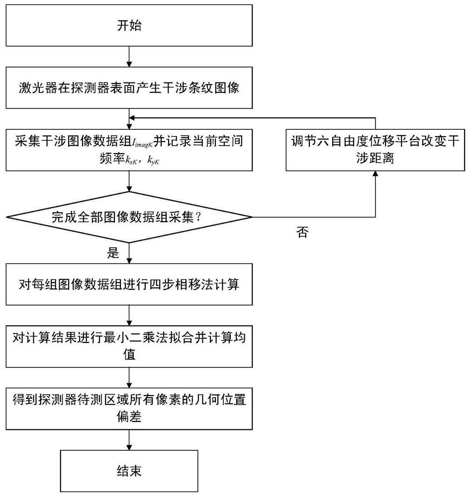
[0054] The following is attached figure 1 The present invention is described in detail with specific examples.

[0055] Step 1: Build a dynamic Young's laser interference fringe calibration system

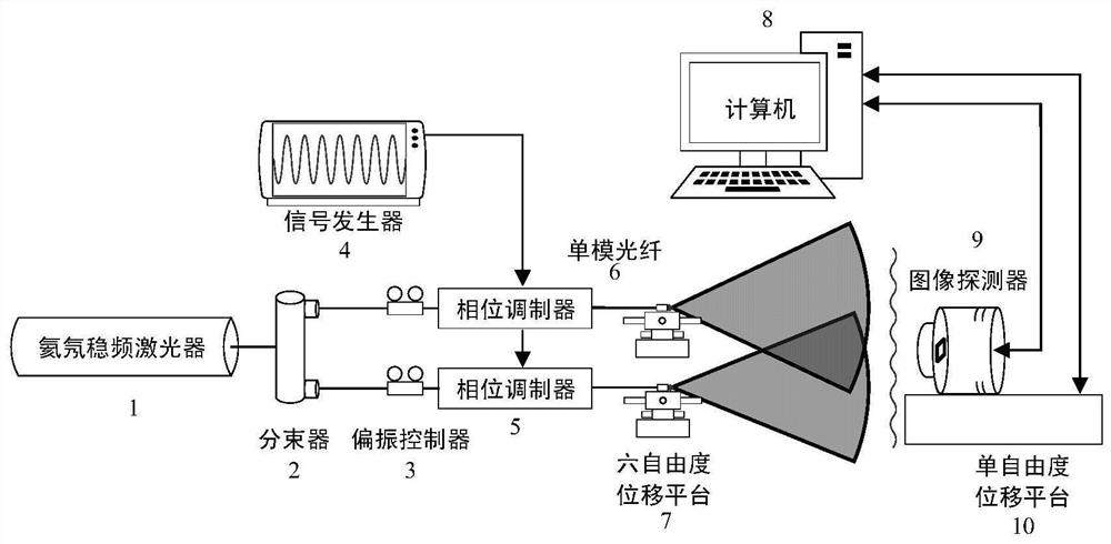
[0056] The composition diagram of the calibration system is attached figure 2 As shown, it consists of a helium-neon laser 1, a fiber beam splitter 2, a polarization controller 3, a signal generator 4, a phase modulator 5, a single-mode optical fiber 6, a six-degree-of-freedom displacement platform 7, a computer 8, an image detector 9 and The single-degree-of-freedom displacement platform 10 is composed. Monochromatic, frequency-stabilized helium-neon lasers produce laser light with a wavelength of 632.8nm. After passing through the laser beam splitter, they are divided into two coherent beams with the same frequency and phase; the interference quality is improved by the polarization controller, and then enter two niobium beams respectively. In the lithium-ion phase modulator, ...


PUM


Abstract

The invention relates to a dynamic Young's laser interference fringe calibration system and a detector pixel geometrical position deviation calibration method. The method includes: building a dynamic Young's laser interference fringe calibration system, and using two high-stable laser beams with frequency difference to generate dynamic dynamics in the far field Interference fringes; control the position and distance of the laser fiber port through a six-degree-of-freedom displacement stage, generate multiple groups of dynamic fringes with different spatial frequencies on the surface of the imaging chip of the image detector, and record the grayscale of each pixel of the detector at different spatial frequencies According to the response value, a sufficient number of fringe light field images are collected; based on the principle of phase shift interference, and using the least squares fitting method, the nanoscale geometric position deviation of the pixel along the x-axis and y-axis of the detector is calculated.

Description

technical field [0001] The invention relates to the field of optical image detector calibration technology and star sensors, in particular to a method for calibrating geometric position deviation of image detector pixels based on the principle of phase shift interference. Background technique [0002] The star sensor is a high-precision space attitude measurement device with the star as the reference system, the starry sky as the working object, and the optical sensitive components as the core. The star sensor detects the azimuth and distance between star point images at different positions on the celestial coordinate system and performs star map capture and identification, and determines the satellite attitude and optical axis by solving its own position relative to the stars in the celestial coordinate system Pointing or target pointing, providing accurate space orientation and reference for aerospace vehicles such as satellites, intercontinental strategic missiles, and sp...

Claims


Application Information

Patent Timeline
Patent Type & Authority Patents(China)
IPC IPC(8): G01C25/00
CPCG01C25/00
Inventor 袁利王立武延鹏张承钰王苗苗郑然王晓燕程会艳钟俊
Owner BEIJING INST OF CONTROL ENG
Why Eureka
Try Eureka