Magnetron

a technology of magnets and electrons, applied in the field of magnets, can solve the problems of demagnetization, low serviceability of magnets, and cost increase, and achieve the effects of improving electron efficiency, high efficiency, and enhancing oscillation efficiency

Inactive Publication Date: 2006-04-04
PANASONIC CORP
View PDF7 Cites 14 Cited by
  • Summary
  • Abstract
  • Description
  • Claims
  • Application Information

AI Technical Summary

Benefits of technology

[0016]In order to solve the problems encountered in the above-mentioned conventional magnetron, the present invention is ...

Problems solved by technology

As a result, improving the oscillation efficiency of the conventional magnetron leads to cost increase.
This causes a problem wherein the magnetron is not compatible with already available products and also causes a problem wherein the serviceability of the magnetron becomes low during repair or the like.
This causes ...

Method used


Image

  • Magnetron
  • Magnetron
  • Magnetron

Examples


embodiment 1

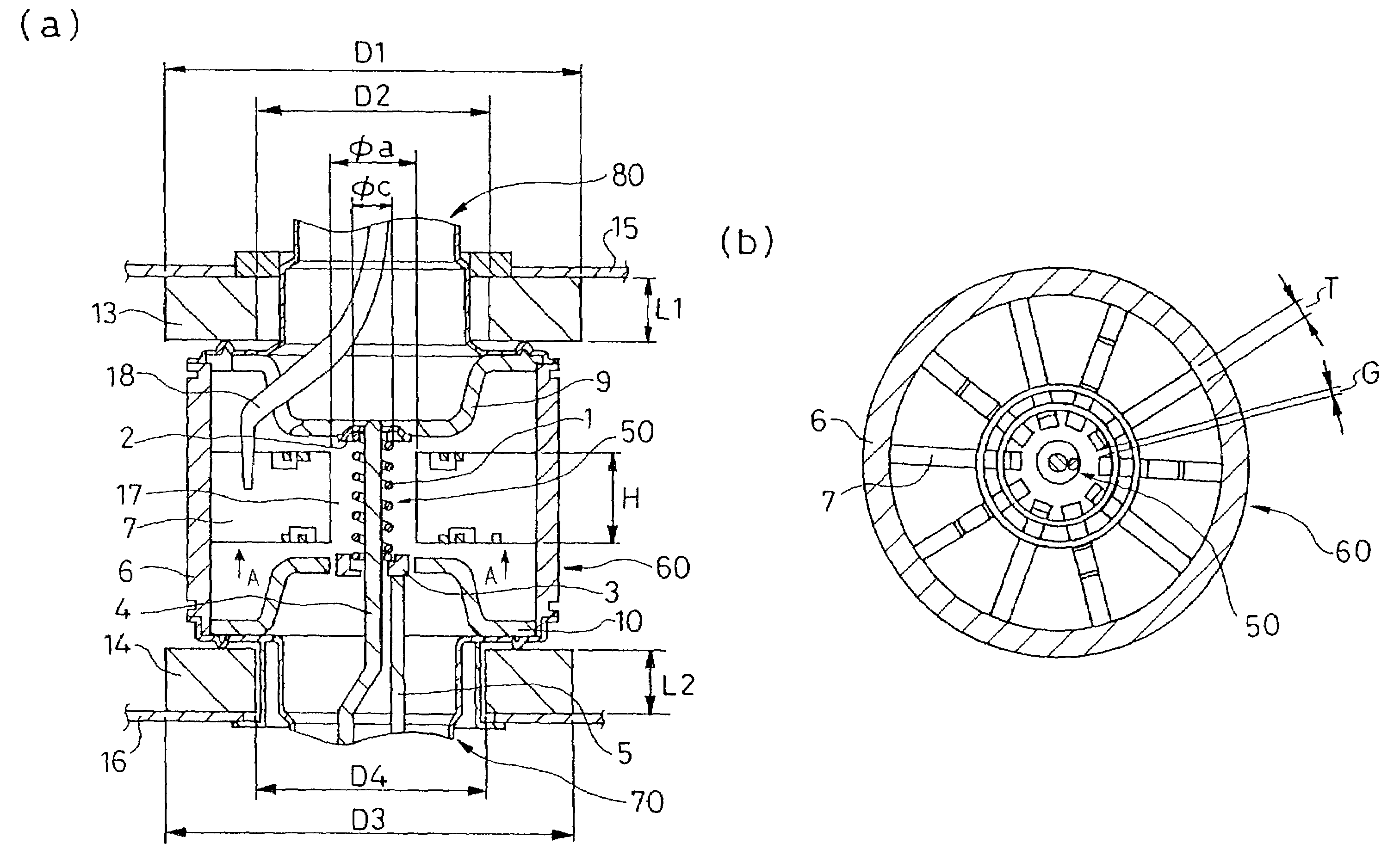
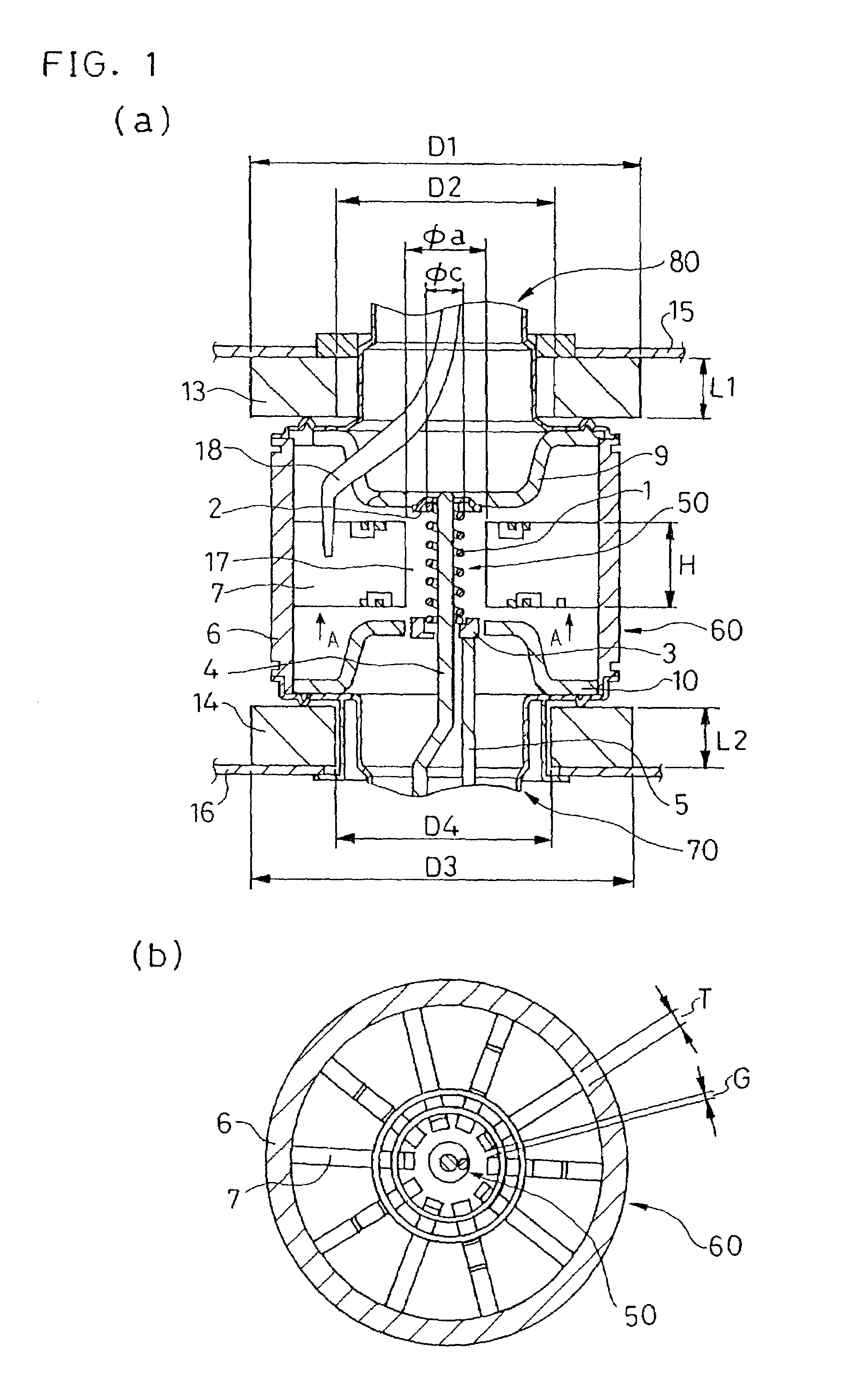
[0053]FIG. 1 is a magnified sectional view showing the main portion of a magnetron in accordance with Embodiment 1 of the present invention. A portion (a) of FIG. 1 is a side sectional view showing the magnetron in accordance with Embodiment 1. A portion (b) of FIG. 1 is a sectional view showing the anode portion and the like in the direction of arrow A in FIG. the portion (a) of 1.

[0054]As shown in FIG. 1, a cathode portion 50 is disposed at the central portion of the magnetron, and an anode portion 60 is disposed around the cathode portion 50. The cathode portion 50 comprises a filament 1, and a center lead 4 and a side lead 5 connected to the filament 1 via end hats 2 and 3, respectively, provided on both ends of the filament 1. The center lead 4 is disposed along the substantially central axis of the coil-shaped filament 1. The anode portion 60 comprises an anode cylinder 6 disposed substantially coaxial with the filament 1 and a plurality of vanes 7. The vanes 7 are disposed so...

embodiment 2

[0075]A magnetron in accordance with Embodiment 2 of the present invention will be described below referring to the accompanying drawings.

[0076]FIG. 7 is a magnified sectional view showing the main portion of the magnetron in accordance with Embodiment 2 of the-present invention. A portion (a) of FIG. 7 is a side sectional view showing the magnetron in accordance with Embodiment 2. A portion (b) of FIG. 7 is a sectional view showing the anode portion and the like in the direction of arrow A in the portion (a) of FIG. 7.

[0077]As shown in FIG. 7, a cathode portion 150 is disposed at the central portion of the magnetron, and an anode portion 160 is disposed around the cathode portion 150. The cathode portion 150 comprises a filament 101, and a center lead 104 and a side lead 105 connected to the filament 101 via end hats 102 and 103, respectively, provided on both ends of the filament 101. The anode portion 160 comprises an anode cylinder 106 and a plurality of vanes 107. The vanes 107...


PUM

PropertyMeasurementUnit
Lengthaaaaaaaaaa
Lengthaaaaaaaaaa
Lengthaaaaaaaaaa

Abstract

A magnetron comprising an anode portion having an anode cylinder and vanes, a cathode portion having a coil-shaped filament, magnetic poles disposed at the upper and lower ends of the filament, ring-shaped permanent magnets made of a Sr ferrite magnet containing La—Co, an input portion and an output portion. The diameter φa of the inscribed circle at the ends of the vanes constituting the anode portion is in the range of 7.5 to 8.5 mm, and the outside diameter φc of the coil-shaped filament 1 constituting the cathode portion is in the range of 3.4 to 3.6 mm.

Description

BACKGROUND OF THE INVENTION[0001]The present invention relates to a magnetron for use in microwave application apparatuses, such as microwave ovens.[0002]A magnetron serving as an electron tube generating microwaves has a relatively high oscillation efficiency and delivers high output with ease. Hence, the magnetron is widely used as a microwave generator for microwave application apparatuses, such as microwave ovens.[0003]A conventional magnetron will be described below.[0004]FIG. 13 is a sectional view showing a conventional magnetron for use in general microwave ovens. As shown in FIG. 13, a cathode portion 250 is disposed at the central portion of the magnetron, and an anode portion 260 is disposed around the cathode portion 250. The cathode portion 250 comprises a filament 201, and a center lead 204 and a side lead 205 connected to the filament 201 via end hats 202 and 203, respectively, provided on both ends of the filament 201. The anode portion 260 comprises a cylindrical an...

Claims


Application Information

Patent Timeline
IPC IPC(8): H01J25/50C23C14/34H01J23/15H01J23/05H01J23/10H01J23/20H01J25/587
CPCH01J25/587H01J23/20H01J23/15
Inventor ISHIIHANDA, TAKANORIAIGA, MASAYUKIKUWAHARA, NAGISA
Owner PANASONIC CORP
Why Eureka
Try Eureka