Light modulation method and apparatus for cold cathode fluorescent lamps

a fluorescent lamp and light modulation technology, applied in mechanical equipment, machine/engine, device details, etc., can solve the problems of low frequency interference, reducing and affecting the efficiency of the mask cycle, so as to increase the life of the piezoelectric transformer

Inactive Publication Date: 2006-04-04
ZIPPY TECH
View PDF7 Cites 12 Cited by
  • Summary
  • Abstract
  • Description
  • Claims
  • Application Information

AI Technical Summary

Benefits of technology

[0010]Another object of the invention is to provide a power control apparatus to modulate the output voltage and current of the piezoelectric transformer without incurring negative effect to the life span of the piezoelectric transformer.
[0011]The invention further uses a PWM control unit to couple the pulse width modulation control method and the aforesaid dynamic frequency alteration control method to adjust the voltage gain of the piezoelectric transformer through a resonant frequency which has altered frequency but unchanged amplitude and the void ratio approach to change output voltage and current of the piezoelectric transformer. The method according to the invention does not frequently charge the piezoelectric transformer or completely stops charge operation. Compared with the conventional burst mode or pulse width modulation control approaches, the invention can increase the life span of the piezoelectric transformer.

Problems solved by technology

Compared with the piezoelectric transformer, in a given power, the magnetic transformer might be thicker and heavier and have a lower efficiency.
Such a technique has two obvious drawbacks, i.e. low frequency interference and the mask cycle have resonant oscillation.
And abrupt change of load also will cause abrupt drop of output voltage.
This affects the life span of the piezoelectric transformer.

Method used


Image

  • Light modulation method and apparatus for cold cathode fluorescent lamps
  • Light modulation method and apparatus for cold cathode fluorescent lamps
  • Light modulation method and apparatus for cold cathode fluorescent lamps

Examples


Embodiment Construction

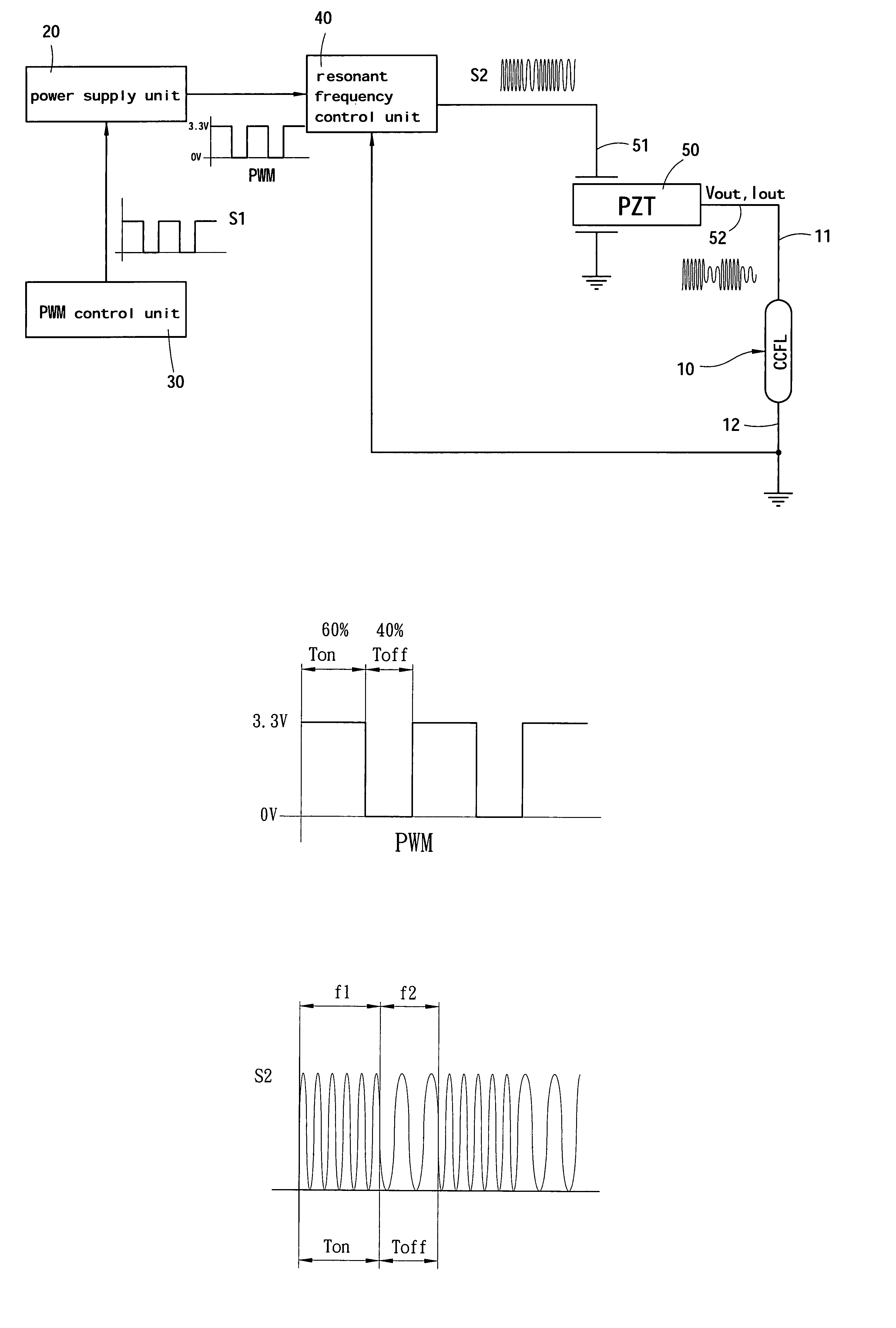
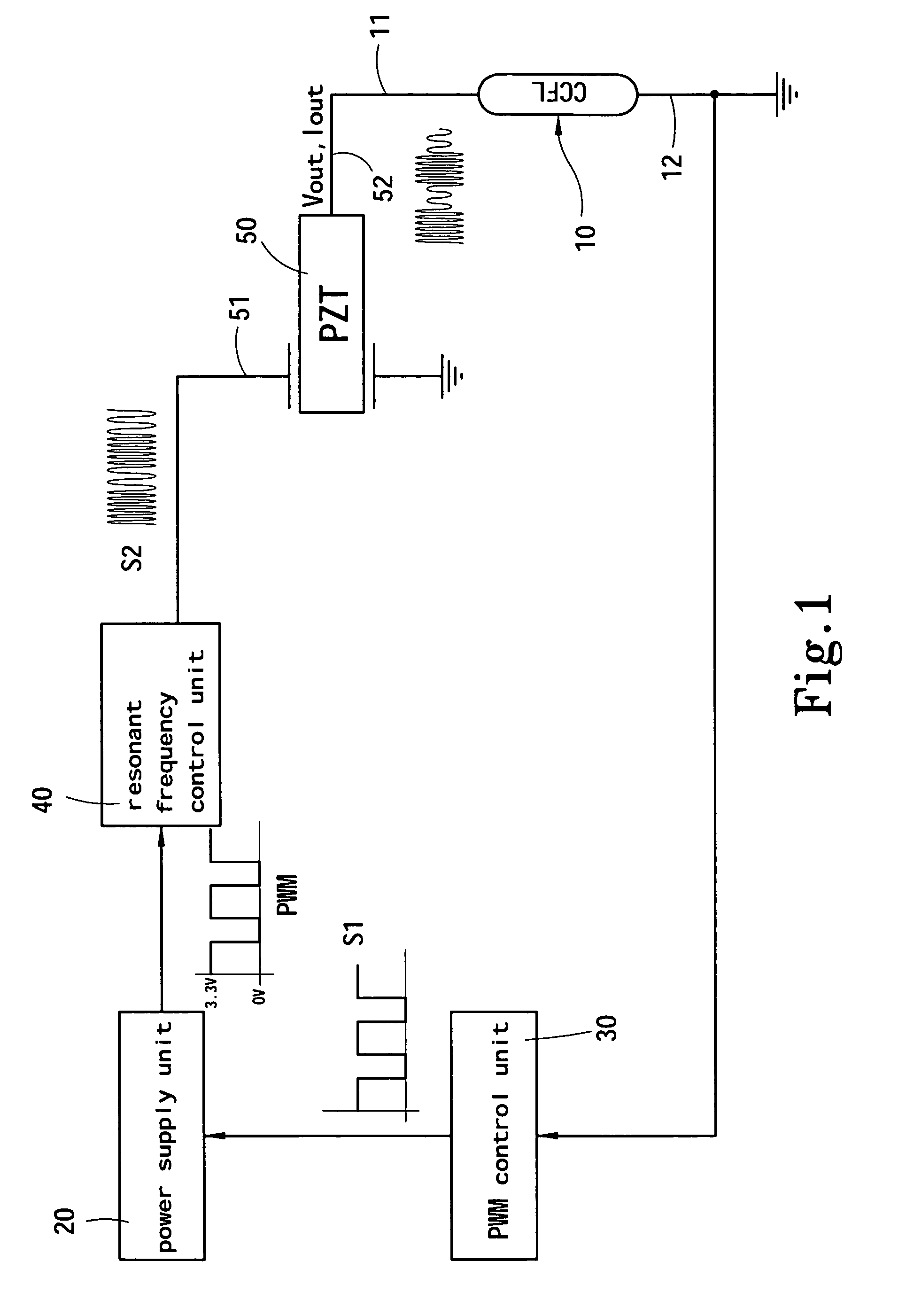
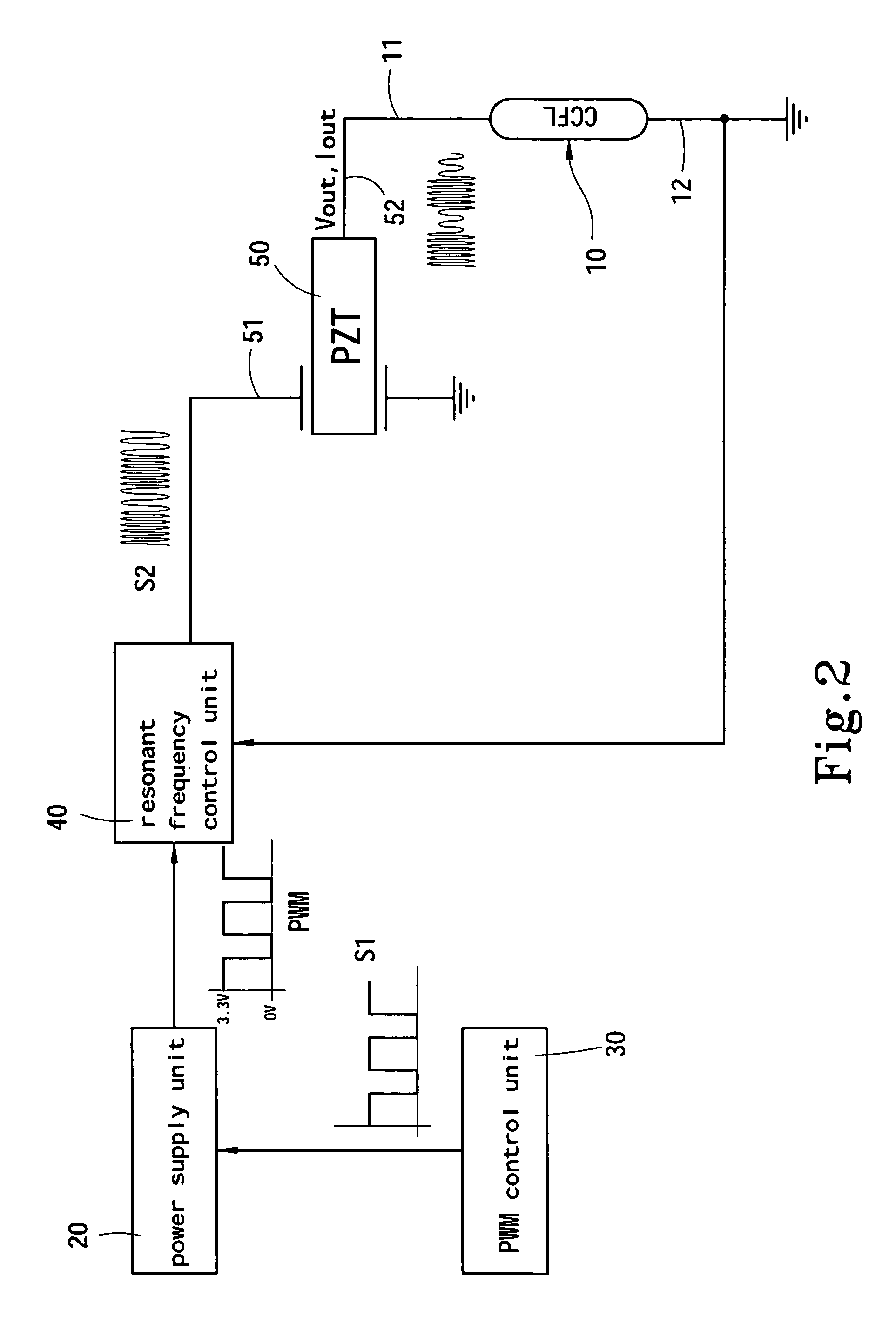
[0020]Please refer to FIG. 1 for a first embodiment of the present invention. The light modulation apparatus according to the invention adopted for use on a CCFL 10 includes:

[0021]a power supply unit 20 to provide DC power required to actuate the CCFL 10 (depending on CCFL specifications, in general a DC power with voltage from 0 volt to several volts);

[0022]a PWM control unit 30 to output a pulse signal S1 through a pulse width modulation technique and through the pulse signal S1 to control the power supply unit 20 to output a pulse width modulation control signal with operation cycles Ton and Toff, namely through the pulse signal S1 to change the void ratio of DC current output from the power supply unit 20 between 0 volt (0 V) and full amplitude (such as 3.3 V). Referring to FIG. 4 for the output waveform;

[0023]a resonant frequency control unit 40 which is a frequency control IC to modulate the pulse width modulation control signal output from the power supply unit 20 to a high f...


PUM


Abstract

A method and apparatus for modulating light of CCFLs that couples frequency alteration and pulse width modulation (PWM) approaches to change output voltage and current of a piezoelectric transformer to modulate the luminosity of a CCFL. The invention includes a PWM controller to alter operation cycle and a frequency control IC to change resonant frequency that drives the piezoelectric transformer at different operation cycles thereby to modulate the luminosity of the CCFL and improve the life span of the piezoelectric transformer.

Description

FIELD OF THE INVENTION[0001]The present invention relates to a method and apparatus for modulating light of a cold cathode fluorescent lamp (CCFL) and particularly to a method and apparatus that changes the driving method of a piezoelectric transformer to alter output voltage and power supply of the piezoelectric transformer to modulate the luminosity of the CCFL.BACKGROUND OF THE INVENTION[0002]Ceramic piezoelectric transformer was first introduced in 1956 by C. A. Rosen. Its operation principle is different from the magnetic transformer which functions through transformation of electromagnetic energy. The piezoelectric transformer first transforms electromotive force to mechanical energy (this process is called inverse piezoelectric effect), then the mechanical energy is transformed to electric energy (this process is called positive piezoelectric effect).[0003]The developments of the magnetic transformer and piezoelectric transformer make fabrication of high efficient and small s...

Claims


Application Information

Patent Timeline
Patent Type & Authority Patents(United States)
IPC IPC(8): H05B37/02H01L41/06H05B41/282
CPCH05B41/2822
Inventor CHOU, CHIN-WENCHENG, EDDIEWU, KUANG-MINGCHUNG, CHIN-BIAU
Owner ZIPPY TECH
Why Eureka
Try Eureka