Check patentability & draft patents in minutes with Patsnap Eureka AI!

Control arrangement for an induction motor compressor having at least three windings, a torque-augmentation circuit a starting capacitor and a resistive element

a control arrangement and induction motor technology, applied in the direction of motor/generator/converter stopper, piston pump, dynamo-electric converter control, etc., can solve the problems of high auxiliary equipment cost, increased weight, and running at full speed in the backward direction, so as to improve the starting torque capability

Inactive Publication Date: 2006-04-04
SMITH OTTO J M
View PDF18 Cites 5 Cited by
  • Summary
  • Abstract
  • Description
  • Claims
  • Application Information

AI Technical Summary

Benefits of technology

"The present invention provides a three-phase compressor that can start with improved torque using a single-phase electrical power supply. The compressor has a better power factor and higher efficiency. It includes an electrical motor with three windings connected to the single-phase power supply. A torque augmentation circuit is used to inject current into the third terminal to improve starting torque. The circuit includes a capacitor and an electrical component with resistive characteristics. The invention allows for improved starting and operation of the three-phase compressor using a single-phase electrical power supply."

Problems solved by technology

Such auxiliary equipment is expensive and adds considerable weight.
Also when opening an electrical power switch on a single-phase motor, a high back pressure in some cases can occur, causing the compressor to act like a gas motor and to spin in the backwards direction, with gas flowing from the outlet port to the inlet port.
If the motor is re-energized during this state as a single-phase motor, it may continue to run at full speed in the backwards direction, which is very undesirable.

Method used


Image

  • Control arrangement for an induction motor compressor having at least three windings, a torque-augmentation circuit a starting capacitor and a resistive element
  • Control arrangement for an induction motor compressor having at least three windings, a torque-augmentation circuit a starting capacitor and a resistive element
  • Control arrangement for an induction motor compressor having at least three windings, a torque-augmentation circuit a starting capacitor and a resistive element

Examples


Embodiment Construction

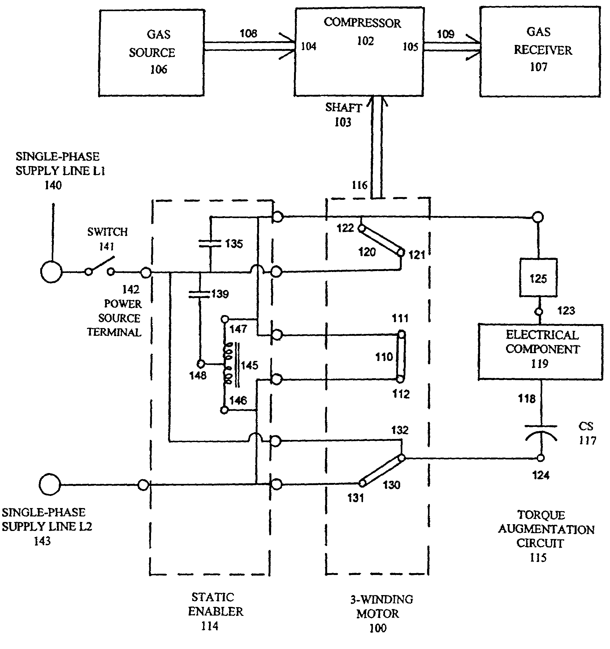
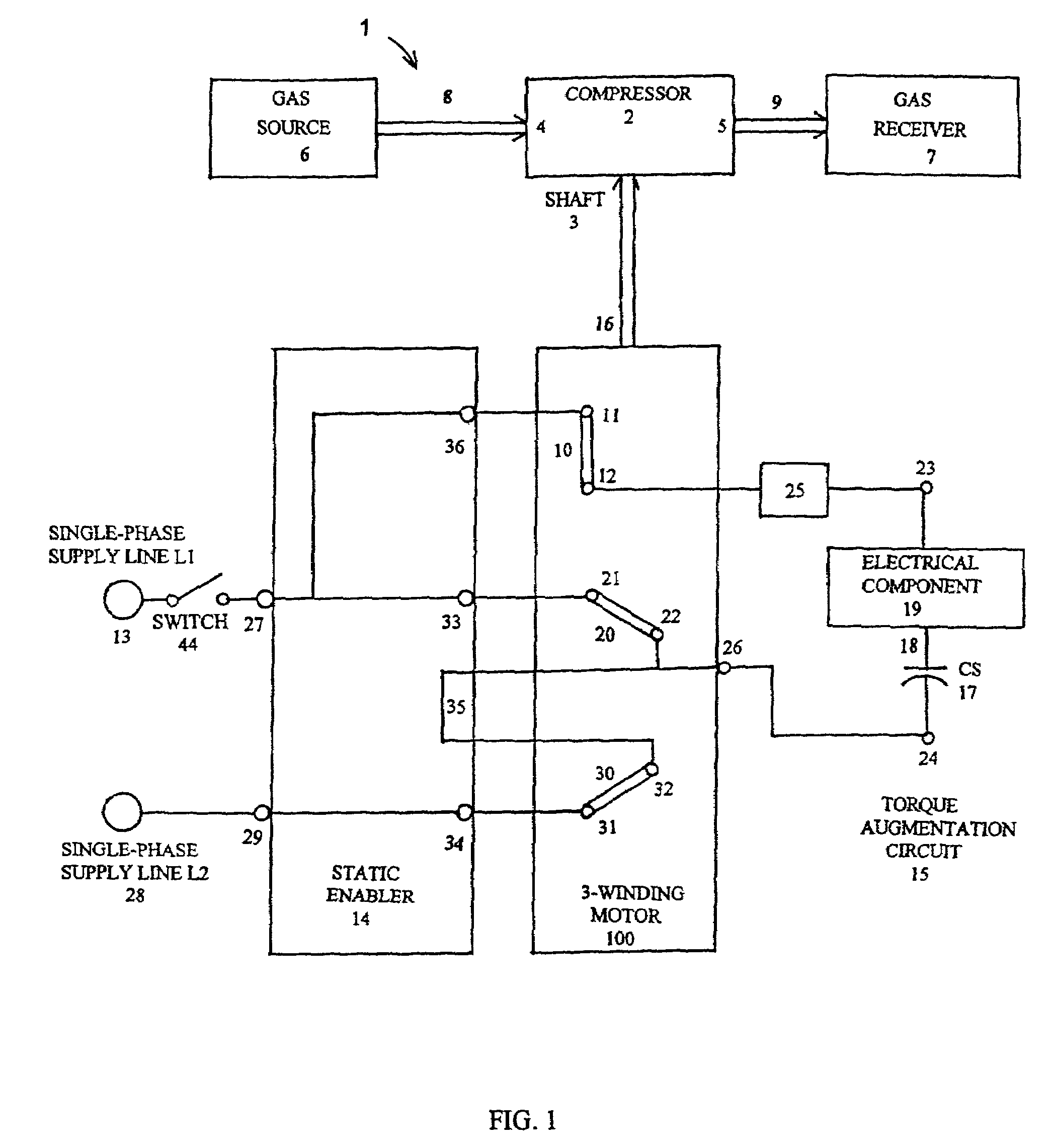
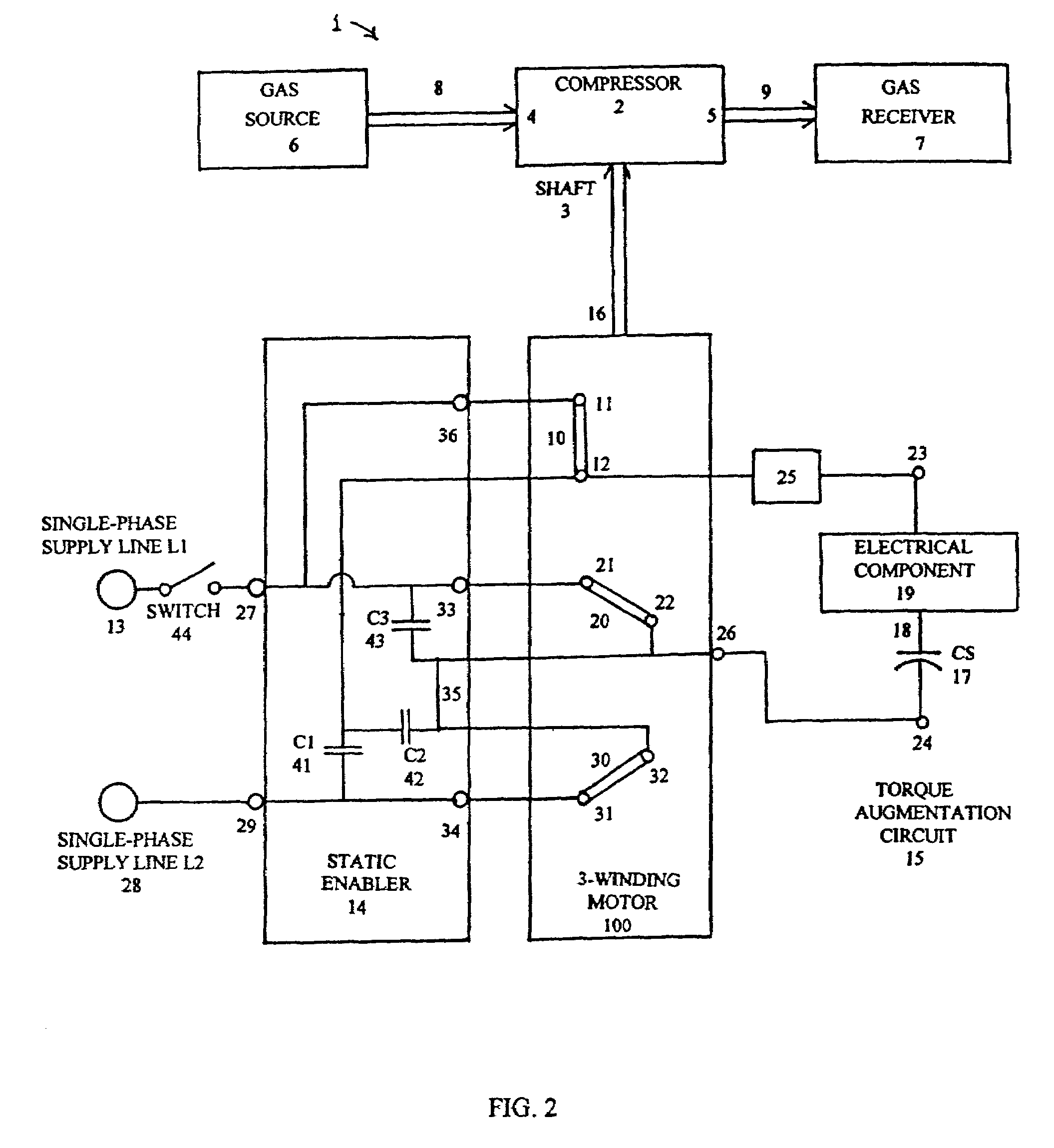
[0023]More in detail, the apparatus and method for driving a three-phase compressor assembly from a single-phase electrical power supply as shown in FIG. 1 consists of an apparatus 1. The apparatus 1 comprises a compressor 2 which is provided with an input power shaft 3, an input gas port 4, and a high-pressure exhaust or output port 5. When the shaft 3 is rotating, the compressor 2 sucks gas from gas source 6 and supplies the gas at a higher pressure into a gas receiver 7 through the use of a pipe 8 from the gas source 6 to the compressor 2 and a pipe 9 from the compressor 2 to the gas receiver 7. The compressor 2 can be either a reciprocating type with pistons, or a rotating scroll type run at approximately constant speed. The gas source 6 can be an evaporator as for example in an air conditioner, heat pump, or refrigerator. The gas receiver 7 can be the condenser in an air conditioner, heat pump or a refrigerator. Alternatively, the gas source 6 can be the atmosphere and the gas ...


PUM


Abstract

Apparatus for driving a three-phase compressor assembly from a single-phase electrical power supply having first and second power lines, said three-phase compressor assembly comprising a compressor having a rotatable shaft, an electrical motor having a rotatable shaft coupled to the rotatable shaft of the compressor, the electrical motor having at least first, second and third motor windings and having at least first, second and third terminals connected to the first, second and third windings, means adapted to connect the first and second power lines of the single-phase power supply to the first and second terminals and a torque augmentation circuit for injecting current into the third terminal and including a capacitor and an electrical component in series with the capacitor, said electrical component having resistive characteristics and having means for essentially interrupting the current being injected into the third terminal.

Description

[0001]The present invention is directed to an apparatus and method for driving a three-phase compressor assembly from a single-phase electrical power supply and more particularly to the starting and running of such a three-phase compressor assembly from such a supply.BACKGROUND OF THE INVENTION[0002]Three-phase air-conditioner compressors are utilized because they have high efficiency. When a single-phase electrical power supply is all that is available for driving such a three-phase compressor, it has been necessary to utilize auxiliary equipment such as starting timers, contactors, and capacitors. Such auxiliary equipment is expensive and adds considerable weight. Single-phase motors heretofore utilized typically are provided with a main winding and a quadrature winding. The quadrature winding has connected to it start and run capacitors. The phase angle of the current in a quadrature winding (lagging the voltage drop in the quadrature winding) due to these capacitors is usually i...

Claims


Application Information

Patent Timeline
Patent Type & Authority Patents(United States)
IPC IPC(8): H02P1/24F04B35/04H02P1/26H02P27/00
CPCF04B35/04H02P27/00H02P1/265
Inventor SMITH, OTTO J. M.
Owner SMITH OTTO J M
Features
  • R&D
  • Intellectual Property
  • Life Sciences
  • Materials
  • Tech Scout
  • Unparalleled Data Quality
  • Higher Quality Content
  • 60% Fewer Hallucinations
Learn More