Broadband antenna with omnidirectional radiation

a broadband antenna and omnidirectional radiation technology, applied in the field of broadband antennas, can solve the problems of unsatisfactory matching of elements over the entire operating band, and achieve the effects of reducing the impedance of the whole, less dispersion, and better matching level

Active Publication Date: 2006-04-04
LICENSING THOMSON +1
View PDF4 Cites 19 Cited by
  • Summary
  • Abstract
  • Description
  • Claims
  • Application Information

AI Technical Summary

Benefits of technology

[0009]According to a first embodiment, the antenna comprises two monopoles making an angle of 90° between themselves. More generally, the value of the angle between two half-monopoles is equal to 180°/N where N is the number of monopoles. According to a variant, the two monopoles make ...

Problems solved by technology

Indeed, although circular monopoles or CDMs (standing for Circular Disc Monopole) are known to be elements that radiate over...

Method used


Image

  • Broadband antenna with omnidirectional radiation
  • Broadband antenna with omnidirectional radiation
  • Broadband antenna with omnidirectional radiation

Examples


first embodiment

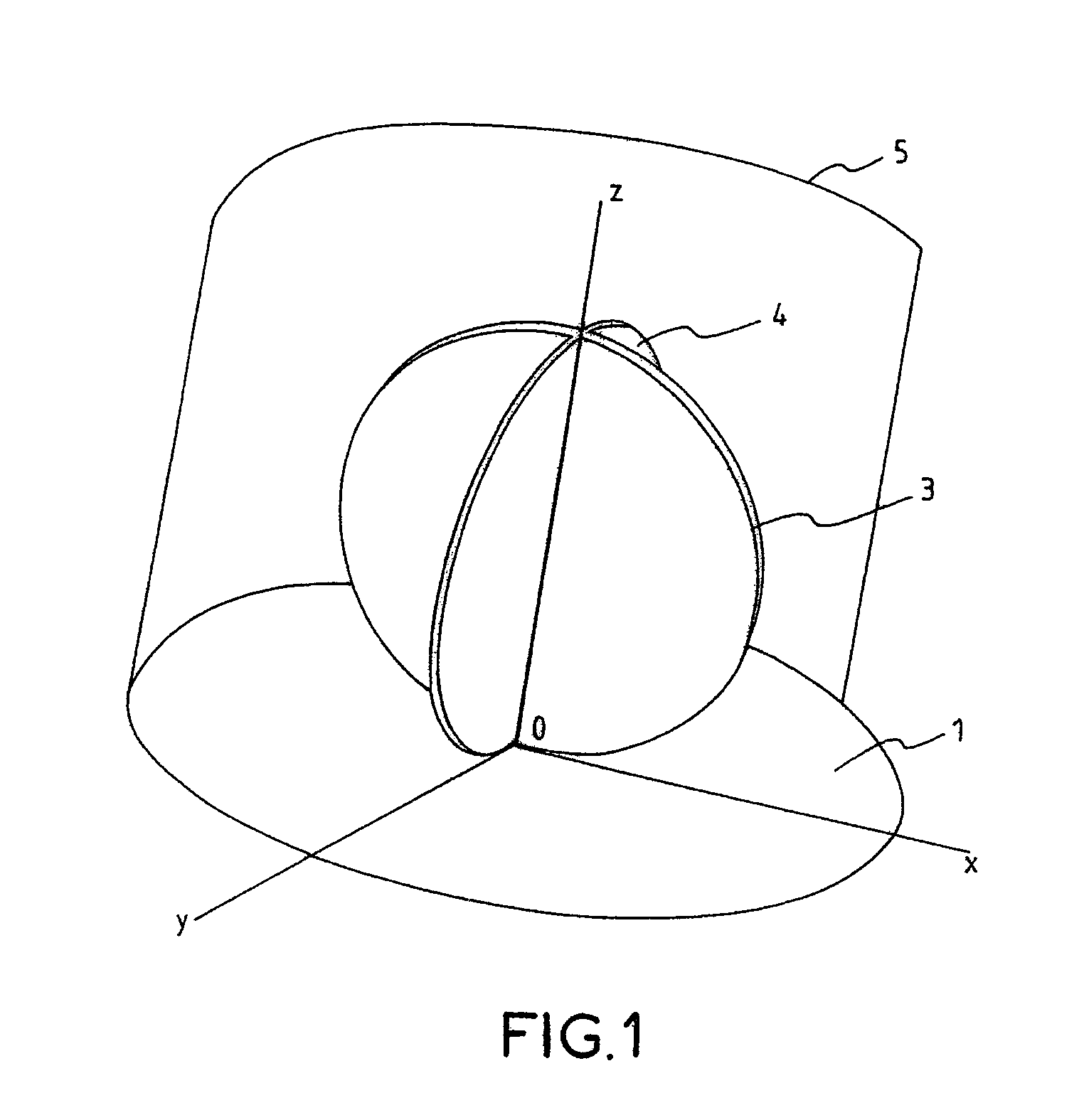
[0021]a broadband antenna with omnidirectional radiation in accordance with the present invention will firstly be described with reference to FIGS. 1 to 3.

[0022]As represented in FIG. 1, two circular discs 3, 4 forming two CDM elements, CDM standing for “Circular Disc Monopole”, have been positioned on a metal earth plane 1, perpendicularly to the latter. As represented in FIG. 1, the two circular discs 3, 4 are nested one within the other according to a common diameter z and are perpendicular to the earth plane 1 which lies in the xoy plane. These two discs 3 and 4 are embodied in a known manner by a metal element. In the embodiment of FIG. 1, the two discs 3 and 4 cross one another in such a way as to form a right angle between themselves.

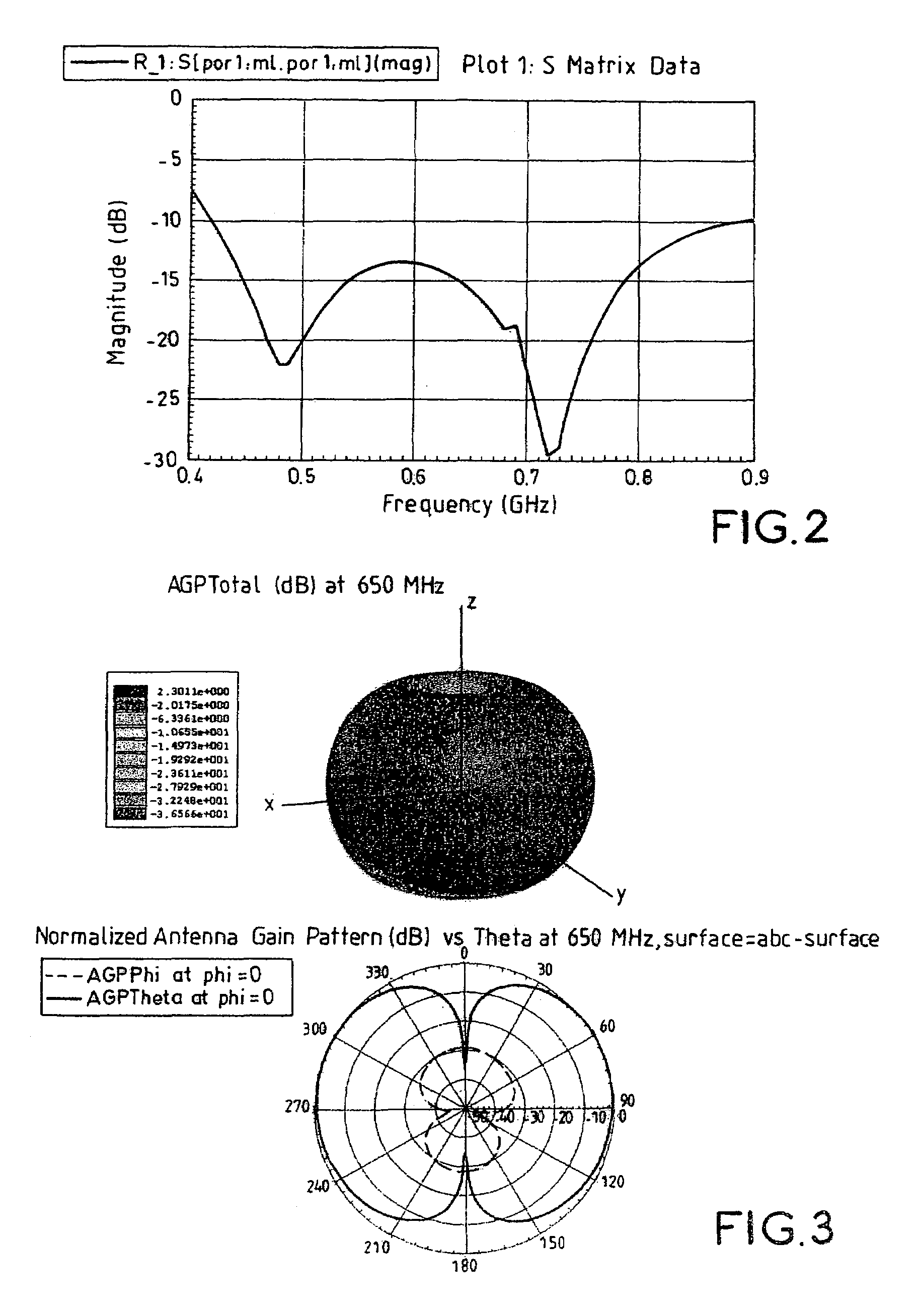
[0023]To simulate the results obtained, an antenna as represented in FIG. 1 has been embodied using two identical metal discs each exhibiting a radius a=90 mm and a thickness e=4 mm. These two discs are nested one in the other, as represented in ...

third embodiment

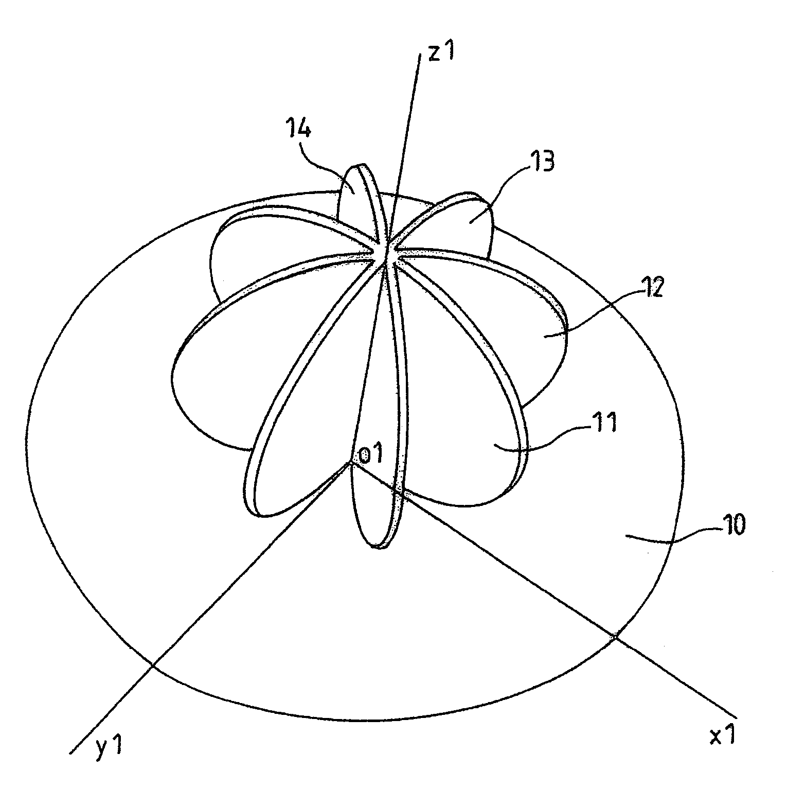
[0028]Finally a third embodiment will be described with reference to FIGS. 7 to 9.

[0029]In this case, the antenna in accordance with the present invention consists of two CDMs (Circular Disc Monopoles), the two discs 21, 22 are positioned with respect to one another in such a way as to have a common diameter according to z2 and are mounted perpendicularly to an earth plane 20 lying in the plane x2 o2 y2.

[0030]In this case, the angles that the two monopole discs make between themselves are not equivalent but for example chosen so that one of the two branches of the discs 22 and 21 makes an angle of 45° while the other branch makes an angle of 135°.

[0031]The antenna represented in FIG. 7 has been simulated in an identical manner to the antennas of FIGS. 1 and 3. The results of the simulations are represented in FIG. 8 which give the matching of the antenna of FIG. 7 with regard to a standardizing impedance of 25 ohms showing that in this case one still obtains matching of possibly up ...


PUM


Abstract

The present invention relates to a broadband antenna with omnidirectional radiation comprising a first circular or semicircular monopole perpendicular to an earth plane, and at least one second circular or semicircular monopole, the monopoles being positioned with respect to one another in such a way as to have a common diameter.

Description

[0001]This application claims the benefit under 35 U.S.C. § 119 (a) of French patent application No. 0301032 filed Jan. 30, 2003.[0002]The present invention relates to a broadband antenna with omnidirectional radiation intended to receive and / or to transmit electromagnetic signals that can be used in the field of wireless communications, more particularly in the case of transmissions for digital terrestrial television.BACKGROUND OF THE INVENTION[0003]Digital terrestrial television will eventually replace analogue television. Within the context of this progress, it is necessary to be able to offer quality reception, even inside houses or apartments. This obligation of inside reception entails constraints on the size of the receiving antenna which should not be bulky.[0004]At present, the antennas used for receiving analogue television signals consist, in the case of terrestrial reception, of a so-called “rake” antenna or Yagi type antenna which is traditionally placed on the roof of ...

Claims


Application Information

Patent Timeline
IPC IPC(8): H01Q9/38H01Q5/00H01Q9/44H01Q9/40H01Q21/29
CPCH01Q21/29H01Q9/40B05B1/24
Inventor THUDOR, FRANCKPINTOS, JEAN-FRANCOIS
Owner LICENSING THOMSON
Why Eureka
Try Eureka