
Image processing apparatus, image processing method and recording medium with color image compacting

a color image and image processing technology, applied in the field of image processing apparatus and image processing method, can solve the problems of similar problems and prolong the color processing time, and achieve the effect of high speed

Inactive Publication Date: 2006-04-04
PANASONIC CORP
View PDF7 Cites 12 Cited by
  • Summary
  • Abstract
  • Description
  • Claims
  • Application Information

AI Technical Summary

Benefits of technology

[0015]To overcome the disadvantages and deficiencies of the prior art as stated above, it is an object of the present invention to provide an image processing apparatus and image processing method to separate an object color image data into command image and photo image, and then to process each of them in such a way that color processing can be done at a high speed.
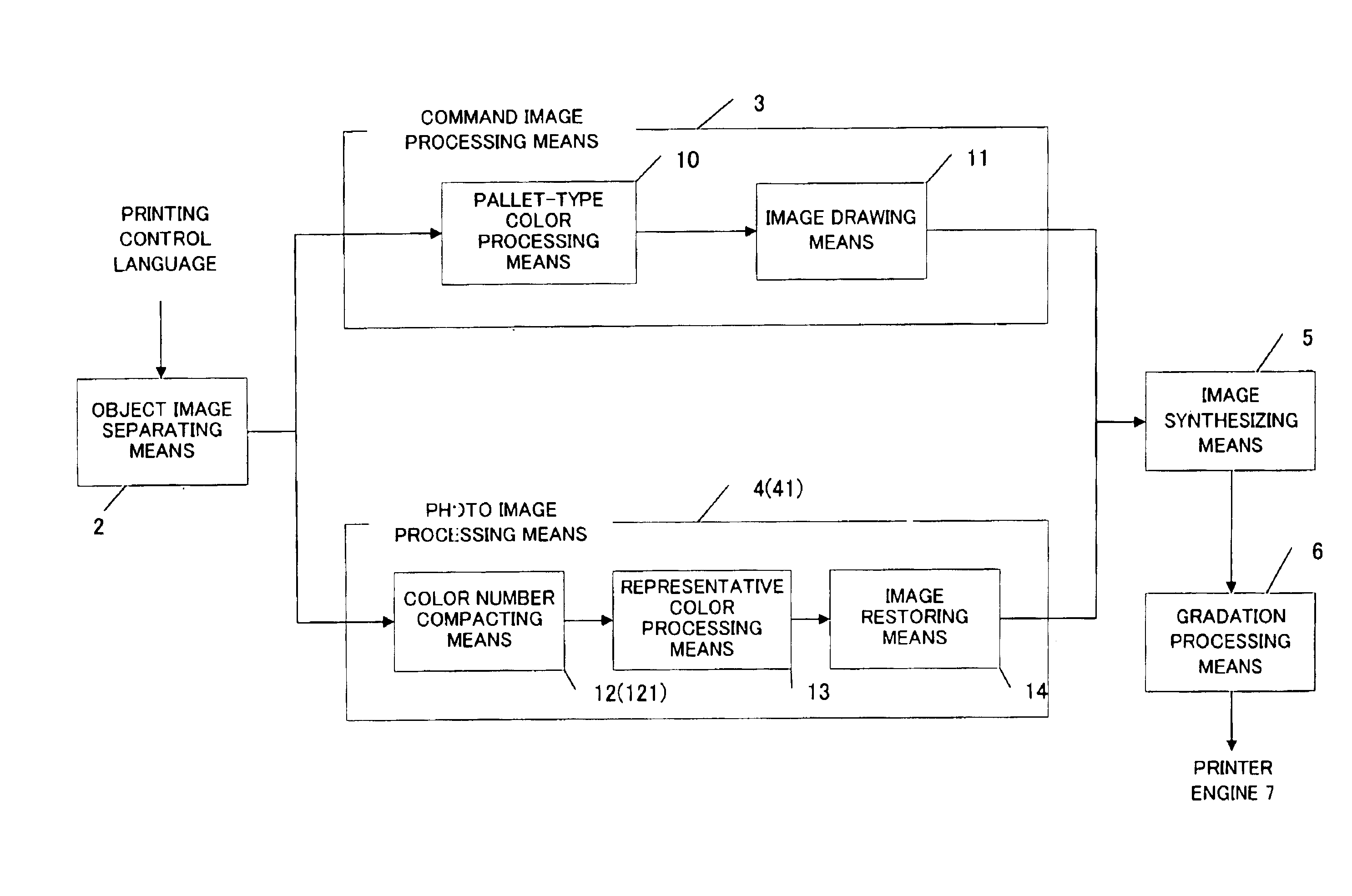
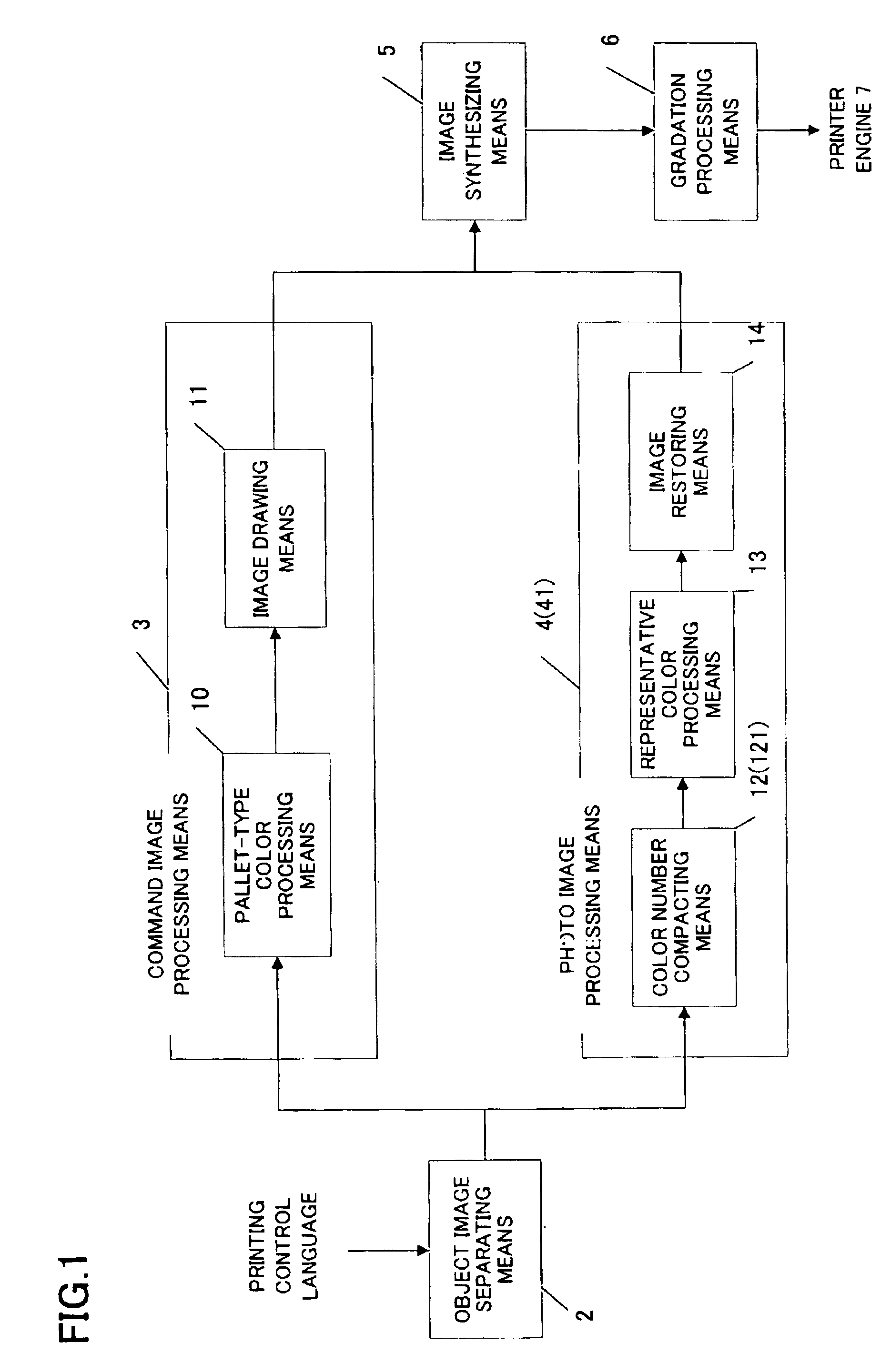
[0018]As for the command images, there is provided command image processing means to color-process color palette information given to a region specified by the drawing command and to generate a first image having color information by the pixel, such as a bitmap image, (hereinafter referred to as a pixel image). Since color-processings to the region are performed in the lump, the required page memory for color-processing is reduced, shortening the time for color-processing.
[0022]Furthermore, image synthesizing means is provided to produce a printing image by synthesizing the first pixel image and the second pixel image, enabling high speed color-processing even if the color image is a combined image of a command image and a photo image.

Problems solved by technology

And because the restored bitmap image is color-processed per pixel, a huge page memory is required to hold bitmap data temporarily, greatly prolonging the color-processing time.
Here, to convert image data described in the display control language into data suitable for display in the display unit or to process image data described in the GDI control language by the GDI, a problem similar to the case where image data described in the printing control language is handled as above takes place.

Method used


Image

  • Image processing apparatus, image processing method and recording medium with color image compacting
  • Image processing apparatus, image processing method and recording medium with color image compacting
  • Image processing apparatus, image processing method and recording medium with color image compacting

Examples


embodiment 1

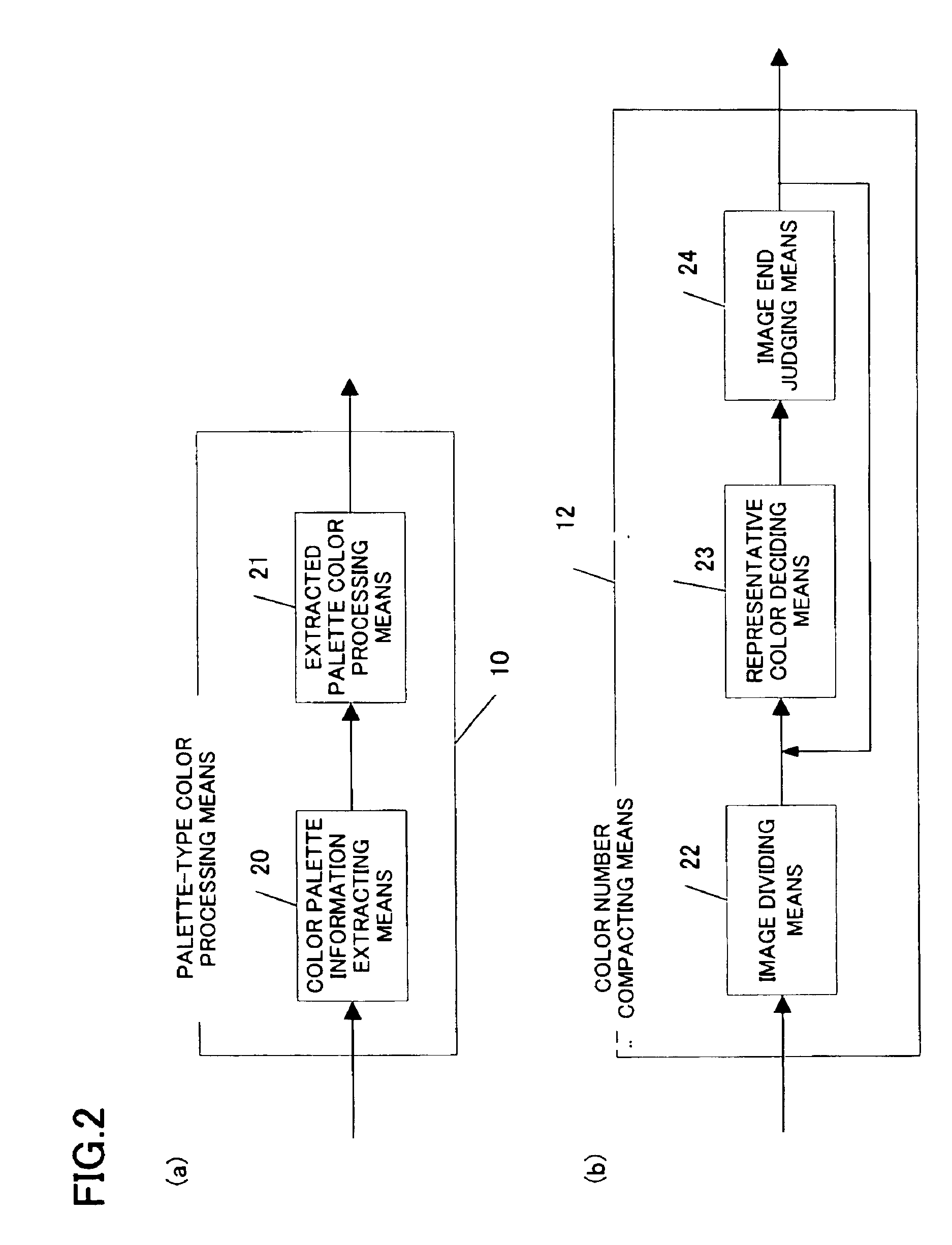
[0046]FIGS. 1, 2 and 3 show arrangements of an image processing apparatus of the first embodiment of the present invention. In the example, a printer is used as output unit and the printing control language is used as outputting control language.

[0047]A printer driver built in a computer converts a color image, an object to be outputted, into printing control language 1, a code (language) the printer can interpret. This printing control language 1 is often provided with such expanded functions as figure drawing along with simple letter printing. Among the typical printing control languages is the page description language as mentioned above.

[0048]Printing control languages generally contain descriptions which tells if the color image is command images generated by the drawing command such as graphic data and text data or photo images having color information by the pixel (bitmap for example).

[0049]In case the color image is a command image, printing control language 1 has informatio...

embodiment 2

[0082]FIG. 8 shows a block diagram of the image processing apparatus according to the second embodiment of the present invention.

[0083]The process up to the steps of object image separating means 2 separating color images described in printing control language 1 into command images and photo images, followed by color processing to generate a bit map image is identical with that in the first embodiment and will not be explained again.

[0084]In the present embodiment, image interpolation means 15 performs interpolation on the bit map image generated by image restoring means 14 of photo image processing means 80.

[0085]In the image processing apparatus of the first embodiment, the number of colors within the blocks are reduced by representative color vectors, and because of this, the edge portions tend to be notched. Furthermore, it is impossible to express a gradation in an area where colors gradually change as in a gradation, and color expression can be flat. The object of the present ...

embodiment 3

[0091]Arrangements of the image processing apparatus according to the third embodiment are shown in FIGS. 1, 12 and 13.

[0092]The process up to the steps of object image separating means 2 separating color images described in printing control language 1 into command images and photo images, followed by color processing of the command image by command image processing means 3 is identical with that in the first embodiment and will not be explained again.

[0093]Color number compacting means 121 within photo image processing means 41 is provided with region adjusting means 120 as shown in FIG. 12. Other than that, the present embodiment is the same as the first embodiment. Furthermore, this region adjusting means 120 is constituted as in FIG. 13.

[0094]The processing performed by this region adjusting means 120 will be explained with reference to FIG. 14.

[0095]Of the blocks generated by image dividing means 22, the image block to be processed here is indicated by block i. The neighboring ...


PUM


Abstract

The following means are adopted in the image processing apparatus according to the present invention. First, an object image separating means separate a color image described in an outputting control language into the command image generated by the drawing command and the photo image generated by the image data having color information per pixel, such as a bitmap data, so that the command image and the photo image are color-processed separately. As for the command images, there is provided command image processing means to color-process color palette information given to a region specified by the drawing command and to generate a first image having color information by the pixel, such as a bitmap image. As for the photo images, there is provided photo image processing means to color-process and generate a second pixel image. In this color-processing, the photo image is divided into a plurality of image blocks. Then at least one kind of colors or representative colors among the colors making up the image block is decided on.

Description

BACKGROUND OF THE INVENTION[0001]1. Field of the Invention[0002]The present invention relates to an image processing apparatus and image processing method for outputting an inputted image data by matching the color specification to the space for reproduced colors in output units such as color printers, facsimiles and displays.[0003]2. Description of the Prior Art[0004]With an upgraded performance of jet printers and digital still cameras, coupled with their affordability in recent years, more home users are interested in printing an image data with a color printer.[0005]One of the most viable ways for home users is to print out an image data displayed and edited on a color monitor connected to a computer. FIG. 20 shows a conceptual diagram of print processing using the conventional printer disclosed in the Japanese patent application laid open under No. 7-25072.[0006]An application 172 installed on a computer 170 usually uses a drawing command of its operating system to produce and ...

Claims


Application Information

Patent Timeline
IPC IPC(8): G06F15/00G06K15/00H04N1/56
CPCG06K15/00H04N1/56G06K2215/0094G06K2215/0002
Inventor WATANABE, TATSUMIKOJIMA, AKIOKUWAHARA, YASUHIROKUROSAWA, TOSHIHARUOKU, HIROTAKA
Owner PANASONIC CORP
Learn More