Method and apparatus for determining the position of an x-ray cone beam produced by a scanning electron beam

a scanning electron beam and cone beam technology, applied in the field of laser or computed tomography imaging, can solve the problem of motion of the electron beam and dri

Inactive Publication Date: 2006-04-04
ANNIS MARTIN
View PDF13 Cites 65 Cited by
  • Summary
  • Abstract
  • Description
  • Claims
  • Application Information

AI Technical Summary

Benefits of technology

[0009]An object of the present invention is to provide a method and apparatus for more precisely determining the source location of the x-ray cone beam in a Laminography system.

Problems solved by technology

However, there is always the possibility that the motion of the electron beam will drift and not be precisely at the required location for each period of time.

Method used


Image

  • Method and apparatus for determining the position of an x-ray cone beam produced by a scanning electron beam
  • Method and apparatus for determining the position of an x-ray cone beam produced by a scanning electron beam
  • Method and apparatus for determining the position of an x-ray cone beam produced by a scanning electron beam

Examples


Embodiment Construction

[0019]The present invention is a method and apparatus for improving the precision of a Laminography or CT imaging system by determining more precisely the location of the x-ray source at several times while the x-ray source while it traverses across the x-ray target.

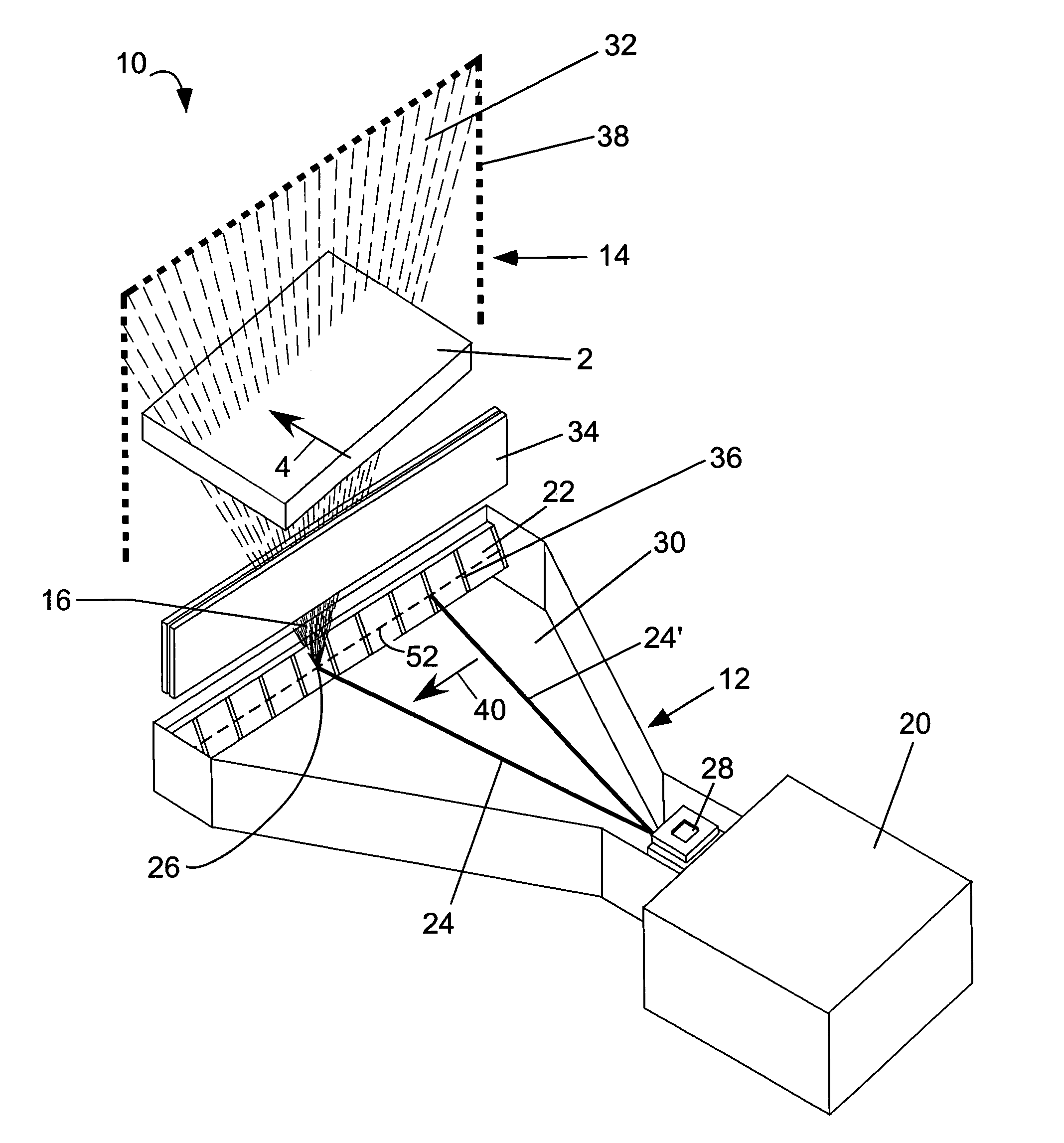
[0020]A Laminography system 10 incorporating the present invention is shown in FIG. 1. The system 10 comprises a source / detector assembly that includes an x-ray source 12 and a detector assembly 14 fixed relative to each other. The object being inspected 2 moves, preferably linearly, between the x-ray source 12 and detector assembly 14, as at 4.

[0021]An x-ray source 12 that can be employed by the present invention is disclosed in U.S. Pat. No. 6,628,745, incorporated herein by reference. The x-ray source 12 uses a narrow pencil beam 24 of high-energy electrons from a DC source of electrons 20 through a vacuum chamber 30 and directed to a linear target 22. The target 22 may be a thin layer of gold plated onto a suitable s...


PUM


Abstract

A Laminography system with x-ray source and a detector assembly. The x-ray source uses a narrow, deflected pencil beam to scan to a linear target. An x-ray cone beam detected by the detector assembly is produced where the electron beam strikes the target. The target is a layer of high-emitting material that is partitioned with narrow regions of low-emitting material, where the low flux intensity is sufficiently low to be easily distinguished from the flux intensity of the high-emitting material. The target may be constructed as a discontinuous layer of high-emitting material applied to a substrate of low-emitting material, or as strips of low-emitting material applied to a continuous layer of high-emitting material.

Description

CROSS-REFERENCES TO RELATED APPLICATIONS[0001]The applicant wishes to claim the benefit of U.S. Provisional Patent Application No. 60 / 543,472, filed Feb. 11, 2004 for SEGMENTED X-RAY SOURCE in the name of Martin Annis.STATEMENT REGARDING FEDERALLYSPONSORED RESEARCH OR DEVELOPMENT[0002]Not ApplicableREFERENCE TO A SEQUENCE LISTING, A TABLE, OR A COMPUTER PROGRAM LISTING COMPACT DISK APPENDIX[0003]Not ApplicableBACKGROUND OF THE INVENTION[0004]1. Field of the Invention[0005]The present invention relates to laminography or computed tomography imaging and more particularly to locating the exact location of the source of the x-ray beam at a particular point in time.[0006]2. Description of the Related Art[0007]U.S. Pat. No. 6,628,745, issued to the present applicant, describes an x-ray source with an electron source that provides a pencil beam of electrons, a beam directing assembly that directs the pencil beam along a line that strikes a target. As the electron beam moves along the targe...

Claims


Application Information

Patent Timeline
Patent Type & Authority Patents(United States)
IPC IPC(8): H01J35/08H01J35/30
CPCG01N23/046H01J35/30G01N2223/419H01J2235/086G01N23/044
Inventor ANNIS, MARTIN
Owner ANNIS MARTIN
Why Eureka
Try Eureka