Calculation method for physical body deformation under load propagation
Inactive Publication Date: 2006-04-04
NIHON UNIVERSITY
View PDF5 Cites 8 Cited by
Summary
Abstract
Description
Claims
Application Information
AI Technical Summary
This helps you quickly interpret patents by identifying the three key elements:
Problems solved by technology
Method used
Benefits of technology
Problems solved by technology
However, in order to reproduce deformation or motion of a physical body by CG, the main current is to make the deformation or motion by trial and error such that the deformation or motion looks just as it is or recovery from dynamic picture by a motion capturesystem constituting a big facility and alleviation of artificial load has yet to reach.
Hence, it is conceivable to integrate FEM (Finite Element Method) which is a method of accurately analyzing behavior of a physical body and a CG animationsystem to enable to know a displacement of a structure (object) by external force, however, the integration is not regarded as practical in consideration of a calculation time period, further, there poses a new problem that a CG creator must obtain specialized knowledge of FEM to some degree.
Further, in order to represent behavior of change in the shape of a physical body by computer graphicsanimation in a physically satisfying form, the change can be provided by using the Finite Element Method, however, when gigantic FEM program is integrated to CG animation program which is inherently gigantic, the program becomes further gigantic and there poses a problem that it is necessary to take into account shortening of an operation time period of a computer executing the program and a computer graphic designer must learn and utilize the Finite Element Method which requires specialized knowledge.
Further, according to current CG animation, although motion of a physical body is smooth, deformation of the physical body per se is not taken into consideration and therefore, for example, although a motion per se of a person is smooth, the shape of muscle remains as it is and also in a case moving a vehicle, although the vehicle per se is moved upwardly and downwardly or leftwardly and rightwardly, when the vehicle makes a turn at a curve, force exerted on a tire is not taken into consideration and therefore, in view of picture as a whole, there is unnaturalness in expression.
Method used
Image
Click on the blue label to locate the original text in one second.
Reading with bidirectional positioning of images and text.
Examples
second embodiment
[0076]Although until here, an explanation has been given two-dimensionally of the material agent 2 and the boundary agent 3, next, as a second embodiment, an explanation will be given three-dimensionally of the material agent 2 and the boundary agent 3 as a method of displaying motion of the physical body according to the present invention.
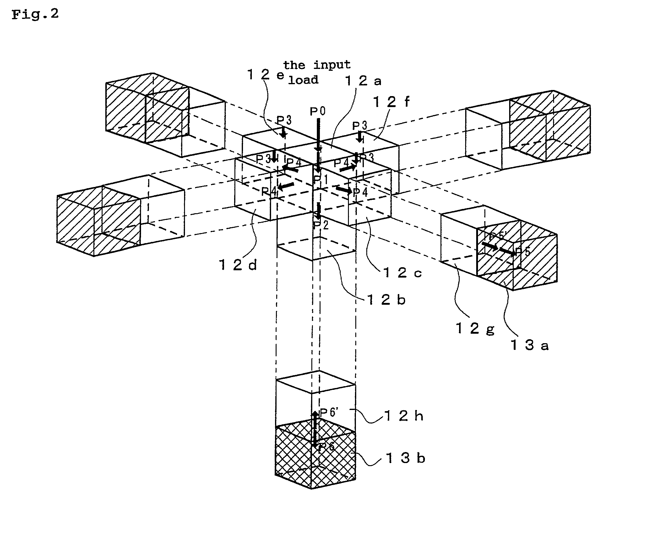
[0077]FIG. 2, mentioned above, is a load propagation operation view of a three-dimensional object physical body (agent) according to the embodiment and notation 12 assumes a material agent and notation 13 assumes a boundary agent.
[0078]For example, when the input load P0 is exerted to a predetermined position of the material agent 12, according to the embodiment, for example, a material agent 12a of a cube is formed, when the material agent 12a is formed, based on the predetermined transmission coefficient α1, the load P1 in the direction the same as that of the input load P0 is transmitted, successively, at a bottom face of the material agent 12a...
first embodiment
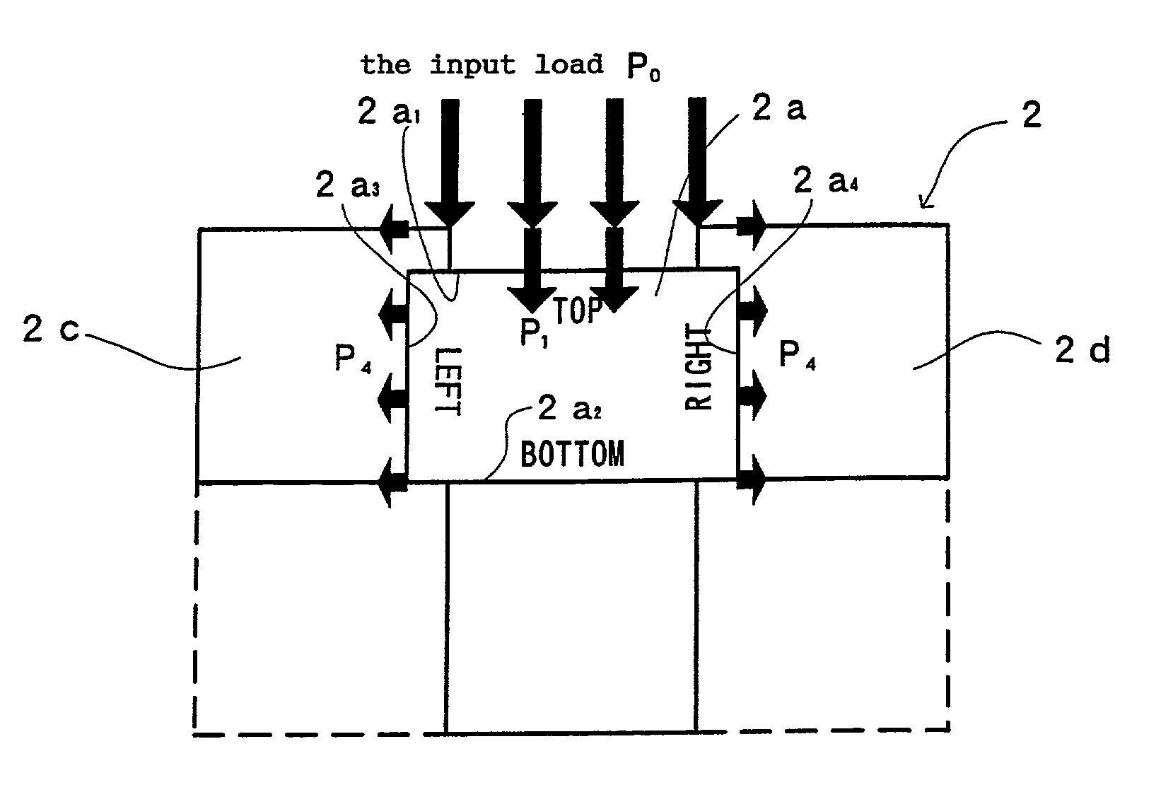
[0079]Further, when the material agent 12a is formed, in a direction the same as the direction of exerting the input load P0, that is, at four side faces of the material agent 12a, friction forces are exerted, similar to the above-described first embodiment, based on the predetermined transmission coefficient α3, the load P3 in the direction the same as that of the input load P0 is transmitted and there are respectively formed material agents 12c, 12d, 12e and 12f having a shape the same as that of the material agent 12a.
[0080]That is, in FIG. 2, at a front side face on the right side of the material agent 12a, the material agent 12c is formed, at a front side face on the left side of the material agent 12a, the material agent 12d is formed, at a rear side face on the LEFT edge side, the material agent 12e is formed and at a rear side face on the right side, the material agent 12f is formed, respectively.
[0081]Further, similar to the above-described formation of agents and load tra...
PUM
Abstract
Method for calculating a deformation of a physical body under a load by forming virtual first to n-th material agents and boundary agents. A predetermined load is transmitted from the virtual first material agent to the virtual second to n-th material agents and to the boundary agents based on a material property and a strain characteristic of the physical body along a load direction and orthogonal to the load direction.
Description
FIELD OF THE ART[0001]The present invention relates to a calculation method for physical body deformation under load propagation for displaying a displacement of a total of a physical body by displaying movements of respective agents constituted by partitioning inside of the physical body into virtual predetermined shapes.BACKGROUND OF THE ART[0002]In recent years, in the field of so-to-speak entertainment such as movie or commercial, CG (Computer Graphics) animation has frequently been used.[0003]However, in order to reproduce deformation or motion of a physical body by CG, the main current is to make the deformation or motion by trial and error such that the deformation or motion looks just as it is or recovery from dynamic picture by a motion capturesystem constituting a big facility and alleviation of artificial load has yet to reach.[0004]In order to know such a displacement of a structure (object) by external force, conventionally, there has been reduced into practice a Finit...
Claims
Application Information
Patent Timeline
Application Date:The date an application was filed.
Publication Date:The date a patent or application was officially published.
First Publication Date:The earliest publication date of a patent with the same application number.
Issue Date:Publication date of the patent grant document.
PCT Entry Date:The Entry date of PCT National Phase.
Estimated Expiry Date:The statutory expiry date of a patent right according to the Patent Law, and it is the longest term of protection that the patent right can achieve without the termination of the patent right due to other reasons(Term extension factor has been taken into account ).
Invalid Date:Actual expiry date is based on effective date or publication date of legal transaction data of invalid patent.

