
Mouse device with tactile feedback applied to housing

a tactile feedback and mouse technology, applied in the field of mouse devices, can solve the problems of user stress and irritation, difficulty in fixing the cursor, and difficulty in steps

Inactive Publication Date: 2006-04-04
IMMERSION CORPORATION
View PDF159 Cites 51 Cited by
  • Summary
  • Abstract
  • Description
  • Claims
  • Application Information

AI Technical Summary

Benefits of technology

[0017]The cursor, being fixed within a three-dimensional object or detail, is possibly free to move within the volume of the object or the detail in an embodiment with the cursor possibly generating a shadow within the object or the detail when drawn out of these without first having been released. The shadow allows that the cursor can be moved more easily into the object or the detail. The invention comprises even a method for marking graphical details by means of a tracking device.

Problems solved by technology

A problem with the control of the cursor to effect the symbols arises when it is difficult to fix the cursor to the symbol in a distinct way to let the touches have the desired effect.
This step takes time and might be difficult and might even give the user stress and irritation.
A further problem, which is related to the use of tracking devices for said object, is that the user requires a simultaneous feature, i.e. to e.g. quickly localize the key for the memorizing function in a program without necessarily having to let the eye scan the display unit.
Ergonometric studies have shown that the user of a computer mouse when continuously using the computer mouse hardly can keep the finger tops over the same spot over a longer period of time.
This is easily understood by ordinary people as some users are easily seized with cramp, writing cramps being a well known complaint.
Furthermore, some people suffer from a lighter or heavier trembling.
Thus the computer mouse with a pin is restricted in its use for a not negligible part of the users of tracking devices.

Method used


Image

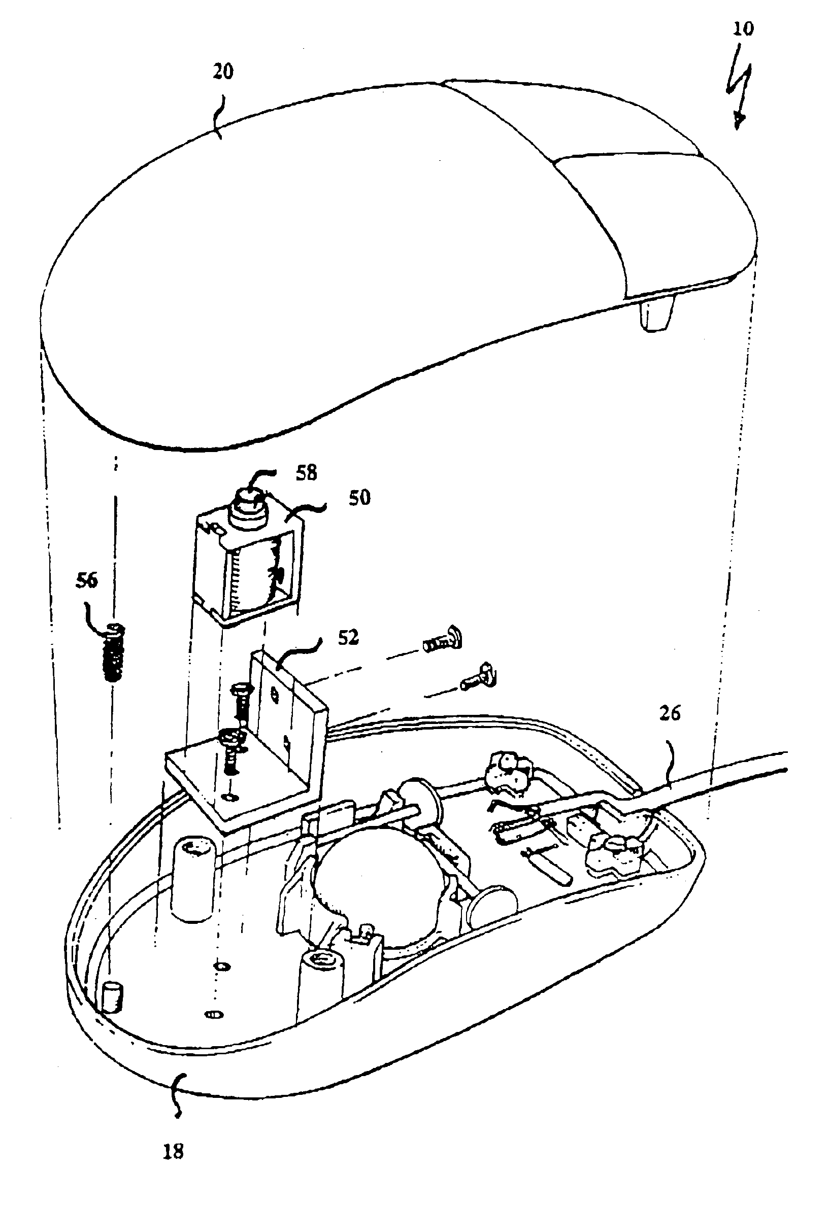
  • Mouse device with tactile feedback applied to housing
  • Mouse device with tactile feedback applied to housing
  • Mouse device with tactile feedback applied to housing

Examples


Embodiment Construction

[0024]The present invention is here described more in detail with alternative embodiments illustrating the technology of the invention and the cognitive, tactile and motoric advantages provided by a tracking device according to the invention.

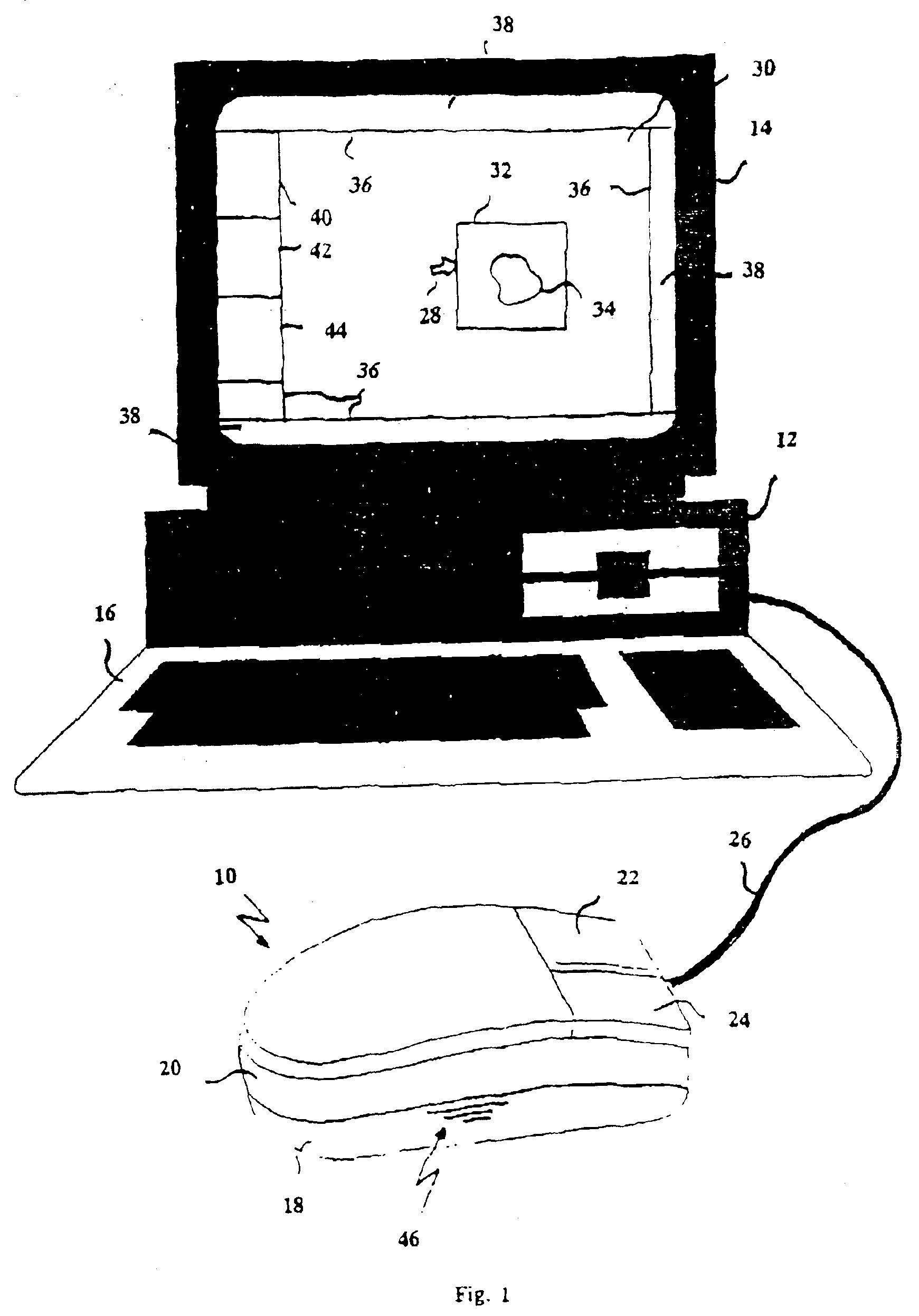
[0025]FIG. 1 illustrates schematically a computer mouse 10 connected to a host unit 12 in form of a computer, here a PC, with a display unit 14 and a key board 16.

[0026]The present invention with its embodiments specifically describes a computer mouse 10, the invention is however generally applicable to a majority of already known tracking devices such as track balls for portable computers, pointers, etc.

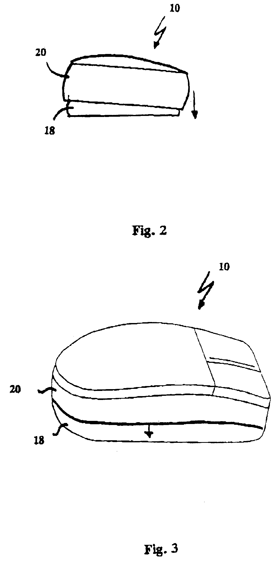
[0027]The computer mouse 10 consists of a casing 20 movable in relation to a bottom portion 18 and the conventional function keys 22, 24. Furthermore, the computer mouse is connected to a host unit 12, 14, 16 by means of a signal cable 26 comprising signal lines for a track balls, here not shown, transmitters in the x and y-direction. Furthermor...


PUM


Abstract

A computer mouse device for tracking user input and providing tactile feedback. A housing includes a lower portion designed to move over a flat surface, and a casing portion engaged by a palm of a user's hand. A sensor is provided within the housing for tracking the motion of the housing with repect to the flat surface, where motion data from the sensor is transmitted to a host computer for updating the status of a cursor on a graphical display displaying one or more graphical details. The mouse device receives over signal lines a sensory feedback signal from the host computer when the displayed cursor interacts with a graphical detail in response to the motion data. An actuator is included within and coupled to the housing and generates motion of the casing in a direction substantially orthogonal to the flat surface, delivering a tactile sensation to the user's palm in response to the sensory feedback signal received over the signal lines.

Description

TECHNICAL FIELD[0001]The present invention relates to a tracking device and a method for a sensory feedback from a cursor status for a cursor with graphical details being scanned or passed in connection with a program or comprising it. More specifically the invention provides a signal to be generated for a sensory feedback generating a movement of the tracking device.BACKGROUND OF THE INVENTION[0002]The user interface in form of a window (Window) as a facility to access special program functions in a data program is found in almost every modern interface. The program basing on the use of windows comprises also function keys in e.g. key rows, screen and display delimiters and icons, so-called graphic symbols.[0003]To achieve access to the functions contained in the symbols a cursor is controlled by means of a tracking device (computer mouse, trackball, pointer, etc.) over a display unit showing the symbols, the function of the symbol being produced by e.g. pressing a key with one or ...

Claims


Application Information

Patent Timeline
IPC IPC(8): G06F9/00G09G5/00G06F3/00G06F3/01G06F3/0346G06F3/0354G06F3/0481G09B23/28
CPCG06F3/016G06F3/0346G09B23/28G06F3/04812G06F3/03543G06F2203/014
Inventor SHALIT, THOMER
Owner IMMERSION CORPORATION
Learn More