Crimping press with contact feed

a technology of crimping press and contact feed, which is applied in the field of crimping press, can solve problems such as distortion of the measurement of crimping for

Active Publication Date: 2006-04-11
KOMAX HOLDING
View PDF13 Cites 18 Cited by
  • Summary
  • Abstract
  • Description
  • Claims
  • Application Information

AI Technical Summary

Benefits of technology

[0004]The apparatus according to the present invention provides a solution for avoiding the disadvantages of the above-described known device, and creates a crimping press whose upper tool does not generate any frictional forces caused by guides.

Problems solved by technology

A disadvantage of this known device is that the die-carrier which is guided in the tool housing causes forces by friction, or that other forces can arise as a result of jamming, and that the forces distort the measurement of the crimping force.

Method used


Image

  • Crimping press with contact feed
  • Crimping press with contact feed
  • Crimping press with contact feed

Examples


Embodiment Construction

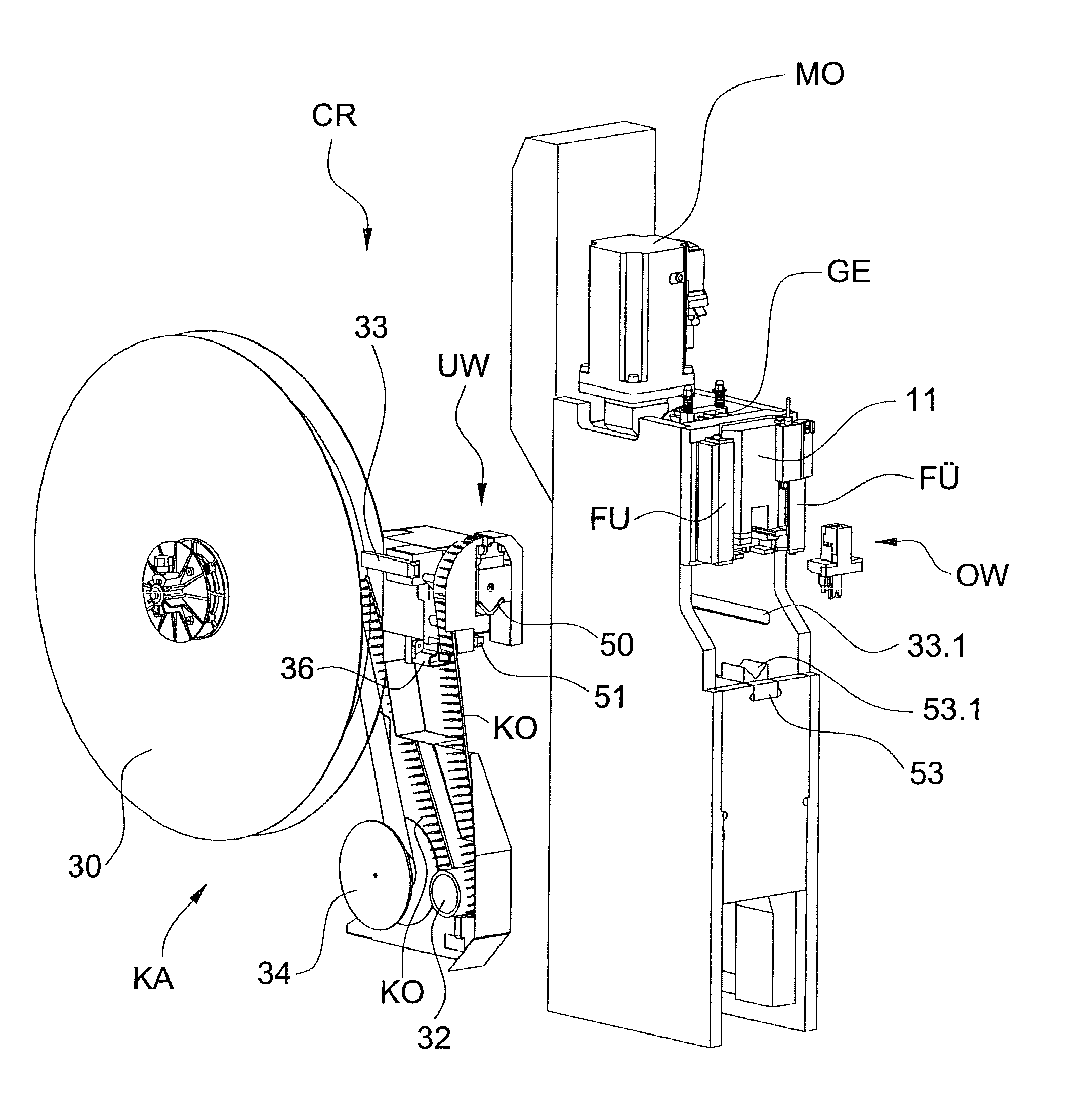
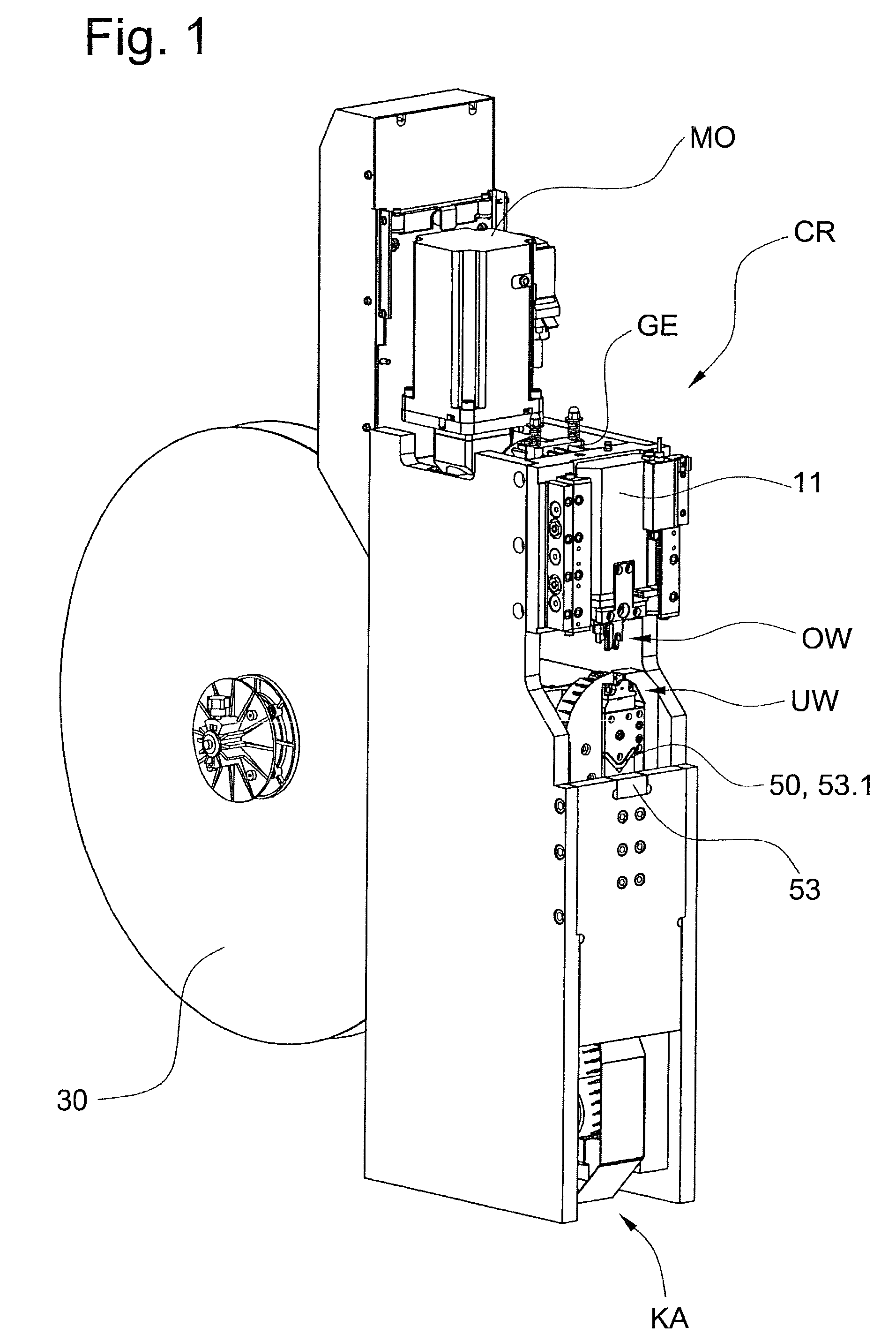
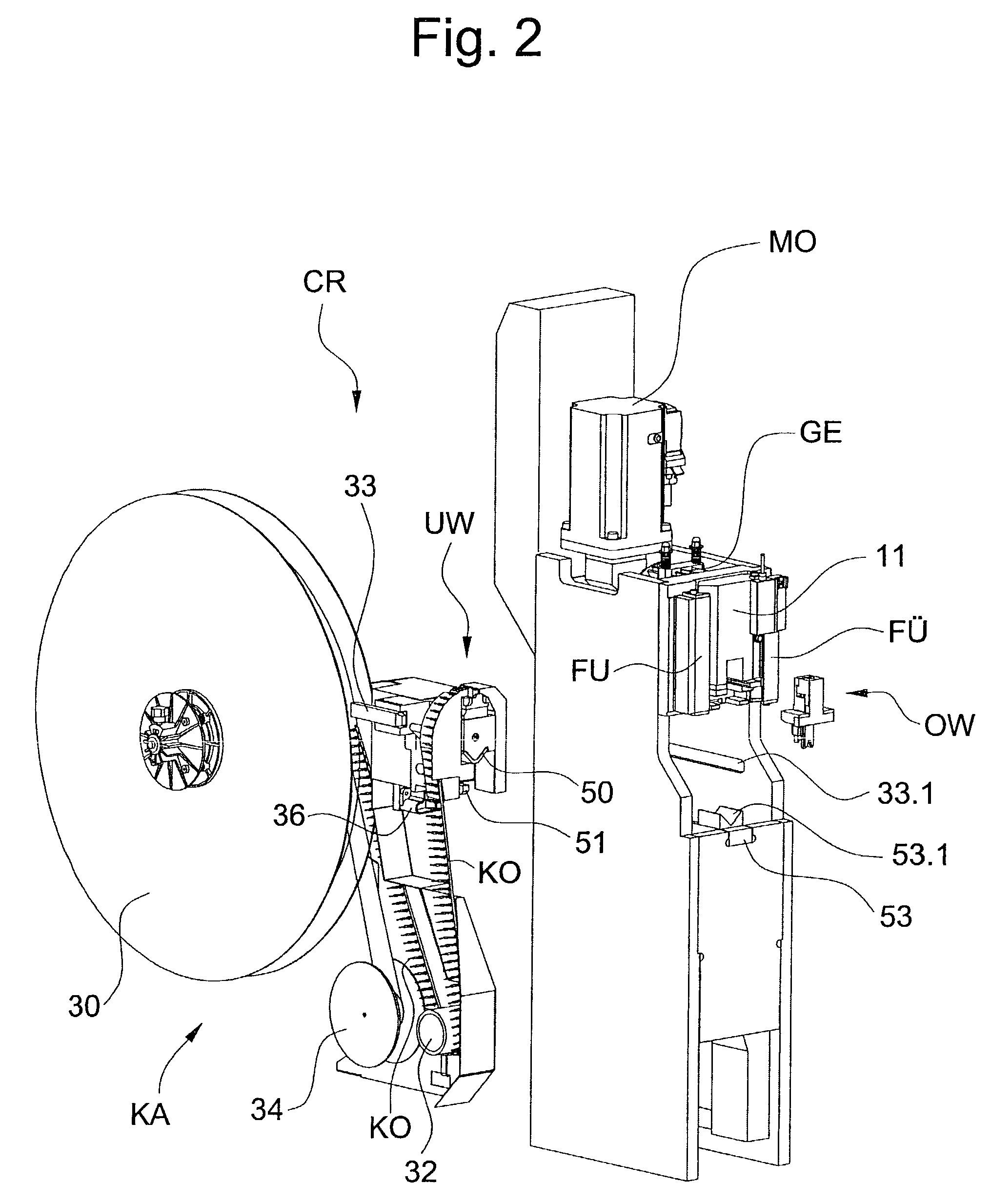
[0016]FIGS. 1 and 2 show a crimping press CR according to the present invention. FIG. 2 shows the crimping press CR with a cassette KA removed and with an upper tool OW removed. A motor MO drives a gear GE. On an output side of the gear GE is an eccentric device which converts the rotational motion of the motor MO and the gear GE into a linear up-and-down motion which can be transmitted to a pressing slider 11 guided by means of guides FU.

[0017]FIG. 3 and FIG. 4 show details of the upper tool OW, which encompasses parts subject to wear such as a wire crimper 1, an insulation crimper 2, and a cutting punch 3. Depending on the crimped contact to be processed, further wear parts and distance plates may be necessary. The wire crimper 1 is bolted tightly to a holder 4, the remaining wear parts inserted, and the upper tool OW closed with a front plate 5. To adjust the height of the insulation crimping, a distancing piece 6 is exchangeable. The cutting punch 3 is supported in the upper too...


PUM

PropertyMeasurementUnit
crimping forcesaaaaaaaaaa
electrically conductingaaaaaaaaaa
rotational angleaaaaaaaaaa

Abstract

A crimping press has a tool receptacle arranged at a lower end of a pressing slider provided with a force-sensing device. The forces arising during the crimping operation are transmitted from the supporting surfaces of an upper tool to several points on the force-sensing device. Provided on each side of an upper fork and held by screws are two collars to which are transmitted, the crimping forces on either side of the supporting surface. With their heads, the screws hold the collars, while with their other ends the screws are engaged with the pressing slider. The collars transmit the crimping forces to the sensor elements of the force-sensing device.

Description

BACKGROUND OF THE INVENTION[0001]The present invention relates to a crimping press for producing a crimped connection by means of an upper tool and a lower tool, in which the upper tool moves in a linear motion to crimp onto an end of a conductor a crimp contact which can be laid on the lower tool.[0002]The European patent specifications EP 0 884 811 and EP 0 902 509 show a crimping press having a motor and a gear arranged on a stand. Also arranged on the stand are first guides on which a crimping bar is guided. A shaft which is driven by the gear has at one end an eccentric pin, and at the other end a resolver for detection of the rotational angle. The crimping bar consists of a slide which is guided in the first guides, and a toolholder with a force sensor and a holding fork. The slide is loosely connected to the eccentric pin, whereby rotational motion of the eccentric pin is converted into a linear motion of the slide. The maximum stroke of the slide is determined by the upper d...

Claims


Application Information

Patent Timeline
Patent Type & Authority Patents(United States)
IPC IPC(8): B23P23/00H01R43/048
CPCH01R43/0486Y10S72/712Y10T29/53265Y10T29/49867Y10T29/53226Y10T29/5147Y10T29/5149Y10T29/49004Y10T29/49185
Inventor IMGRUT, PETERMEISSER, CLAUDIO
Owner KOMAX HOLDING
Why Eureka
Try Eureka