Concrete floor system and method of making floor components

a technology of concrete floor and floor components, which is applied in the direction of girders, joists, building roofs, etc., can solve the problem that none of the above-mentioned prior art patents specifically disclose, and achieve the effect of reducing the cost of labor in building

Inactive Publication Date: 2006-04-11
CLARK RYAN +2
View PDF3 Cites 16 Cited by
  • Summary
  • Abstract
  • Description
  • Claims
  • Application Information

AI Technical Summary

Benefits of technology

[0006]In view of the foregoing, it is a primary objective of the subject invention to provide a unique concrete floor system, which eliminates the use of concrete forms and pouring a concrete floor in place at the building site thereby reducing cost of labor in building the floor. The concrete floor system is easily adapted for mounting next to the inside of the sides of the building's concrete foundation walls and supported on steel or concrete lentals attached to the sides of the foundation walls.
[0007]Another object of the floor system is the floor components can be fabricated off site and delivered on site when the foundation walls are completed. Also, the floor components can be easily removed and replaced. Further, removing floor components allows access under the floor.
[0008]Yet another object of the floor system is the use of different types of concrete beams, which can be cut to a desired length. The beams can be solid pre-cast concrete beams. Also, the beams can be solid pre-cast, pre-tension beams. Further, the beams can be solid post-tension beams. Still further, the beams can be post-tension beams made of a plurality of hollow concrete blocks compressed together. The hollow beams made up of concrete blocks reduce the overall weight of each beam. The ends of solid and hollow concrete beams include recessed end plates, which allow the beams to be cut to size for custom installation. Also, interlocking concrete floor panels can be cut to size for custom installation. The use of individual concrete floor panels, when the floor system is on grade, provides for expansion and contraction due to expansive soils. This feature eliminates cracks, which heretofore occurred in poured concrete slab floors.
[0009]Still another object of the floor system is certain components of the floor system can be produced in a high production standard concrete block machine for reducing the cost of making the components.
[0010]The concrete floor system includes a plurality of parallel concrete beams. The beams can be made of a plurality of hollow concrete blocks for reduced weight and receiving a tension cable therethrough. Also, the beams can be either solid pre-cast beams, or solid pre-cast, pre-tension beams or solid post-tension beams. Opposite ends of the cable are held on end plates inside recessed ends of each beam. The ends of the beams are adapted for mounting on steel or concrete lentals attached to the sides of the foundation walls. The beams can be in a range of 5 to 20 feet and greater in length depending on the dimensions of the concrete floor. A top portion of the each parallel beam is adapted for receiving a plurality of angular shaped floor panels thereon. The floor panels and concrete blocks, used in making up one of the embodiments of the concrete beams, are readily adapted for making in a standard high production concrete block machine.

Problems solved by technology

None of the above-mentioned prior art patents specifically disclose the unique features, combination of structure, function and advantages of the subject concrete floor system as described herein.

Method used


Image

  • Concrete floor system and method of making floor components
  • Concrete floor system and method of making floor components
  • Concrete floor system and method of making floor components

Examples


Embodiment Construction

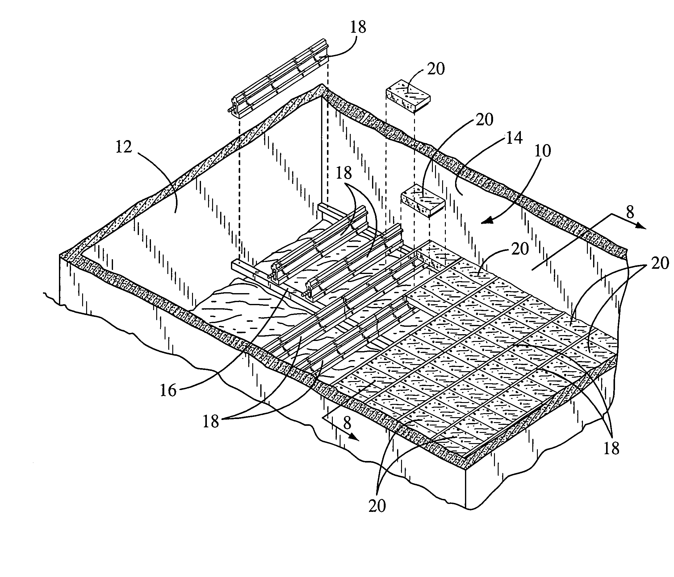
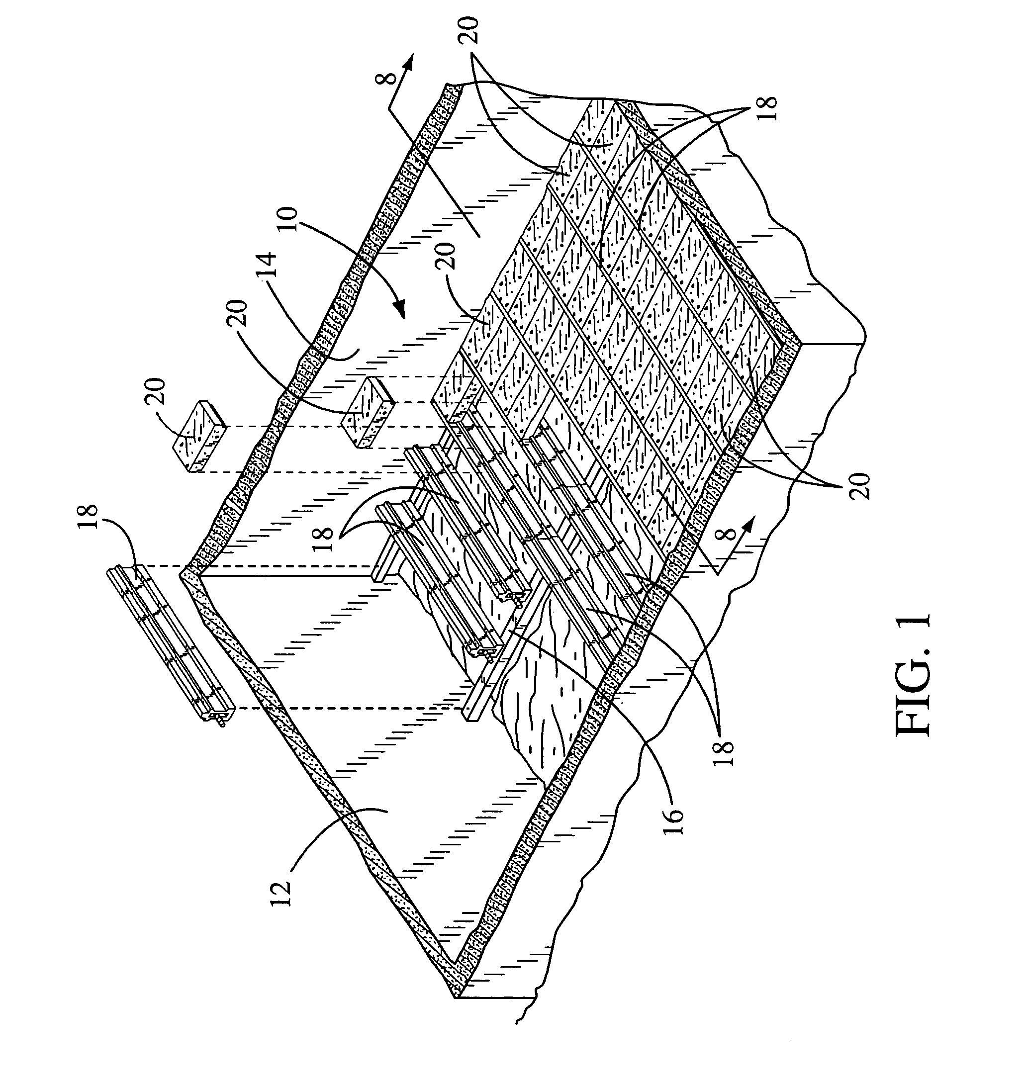
[0027]In FIG. 1, a perspective view of the subject concrete floor system is illustrated and having a general reference numeral 10. The floor system 10 is shown being installed inside a building foundation 12 and mounted next to the sides of foundation walls 14 and on a foundation beam 16. The foundation beam 16 can be a metal “H” or “I” beam, a concrete beam or like.

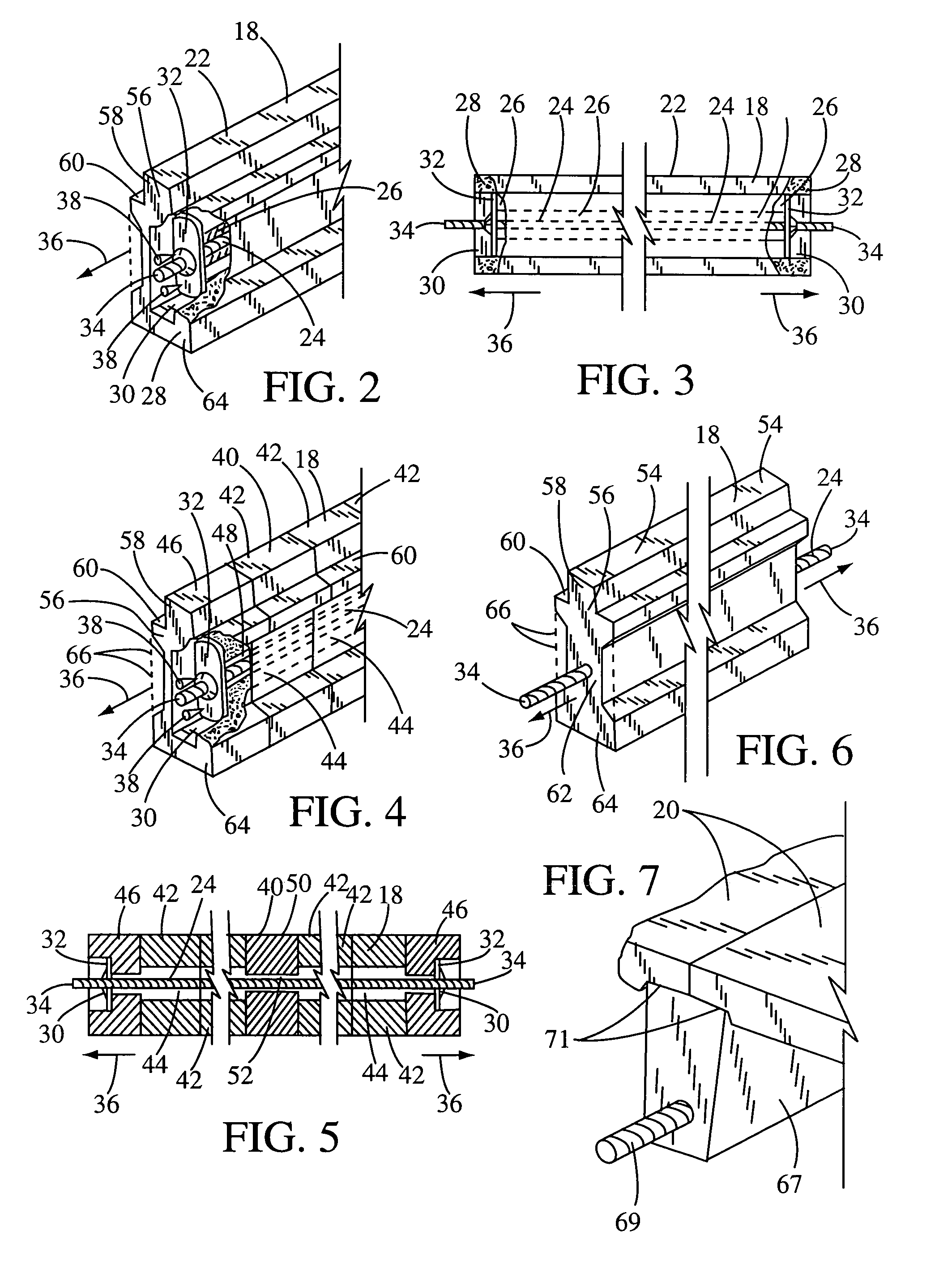
[0028]The floor system 10 broadly includes a plurality of parallel concrete beams 18 and a plurality of angular shaped concrete floor panels 20. The beams 18 can be solid pre-cast beams without tension placed thereon, solid pre-cast, pre-tension beams, solid post-tension beams, or post-tension beams made up of a plurality of hollow concrete blocks. The different embodiments of the beams 18 are shown in FIGS. 2–7. The floor panels 20 are mounted next to each other in an interlocking relationship and on top of a portion of the concrete beams 18 as shown in this drawing. Opposite sides of each floor panel 20 engage the top ...


PUM


Abstract

A concrete floor system used in a building structure and a method of making floor components used with the floor system. The concrete floor system, if installed on grade, provides for expansion and contraction due to expansive soils and eliminates cracks, which heretofore occurred in poured concrete slab floors. The concrete floor system includes a plurality of parallel concrete beams. The beams can be made up of hollow concrete blocks for reduced weight and receiving a tension cable therethrough. Also, the beams can be either solid pre-cast beams, solid pre-cast, pre-tension beams or solid pre-cast, post-tension beams. Opposite ends of the cable are held on end plates inside recessed ends of each hollow beam. The ends of the beams are adapted for mounting next to the inside of the sides of a building foundation wall. The beams can be in a range of 5 to 20 feet and greater in length depending on the dimensions of the concrete floor. A top portion of the each parallel beam is adapted for receiving a plurality of angular shaped floor panels. The floor panels interlock next to the top portion of the beam. The floor panels and concrete blocks, used in making up one of the embodiments of the concrete tension beams, are readily adapted for making in a standard high production concrete block machine.

Description

BACKGROUND OF THE INVENTION[0001](a) Field of the Invention[0002]This invention relates to a concrete floor system and method of making components used in the floor system and more particularly, but not by way of limitation, to a floor system having a plurality of pre-cast beams, or pre-tension beams or post-tension concrete beams used for receiving a plurality of interlocking concrete floor panels. The concrete floor system eliminates the use of building concrete forms, eliminates the pouring of a concrete floor in place and eliminates cracks commonly found when a concrete slab floor is poured on grade and due to the expansion and contraction of expandable soils under the concrete slab.[0003](b) Discussion of Prior Art[0004]In U.S. Pat. No. 2,644,497 to Wilmer et al. and U.S. Pat. No. 3,283,457 to Hart, a clamp with rod is illustrated for holding a plurality of concrete blocks together and a method of forming a pre-stressed concrete plank or beam made up of a plurality of blocks. I...

Claims


Application Information

Patent Timeline
Patent Type & Authority Patents(United States)
IPC IPC(8): E04C5/08
CPCE04B5/046E04C3/26E04C3/22E04B5/08
Inventor CLARK, RYANHUG, LAWRENCE J.MARTINEZ, MICHAEL J.
Owner CLARK RYAN
Why Eureka
Try Eureka