Variable geometry turbocharger with sliding piston

Inactive Publication Date: 2006-04-11
HONEYWELL GARRETT
View PDF20 Cites 33 Cited by
  • Summary
  • Abstract
  • Description
  • Claims
  • Application Information

AI Technical Summary

Problems solved by technology

In piston type variable geometry turbochargers in the prior art, the challenge has been maximizing aerodynamic performance balanced with tolerancing of mating surfaces, particularly of vanes and receiving sl

Method used


Image

  • Variable geometry turbocharger with sliding piston
  • Variable geometry turbocharger with sliding piston
  • Variable geometry turbocharger with sliding piston

Examples


Embodiment Construction

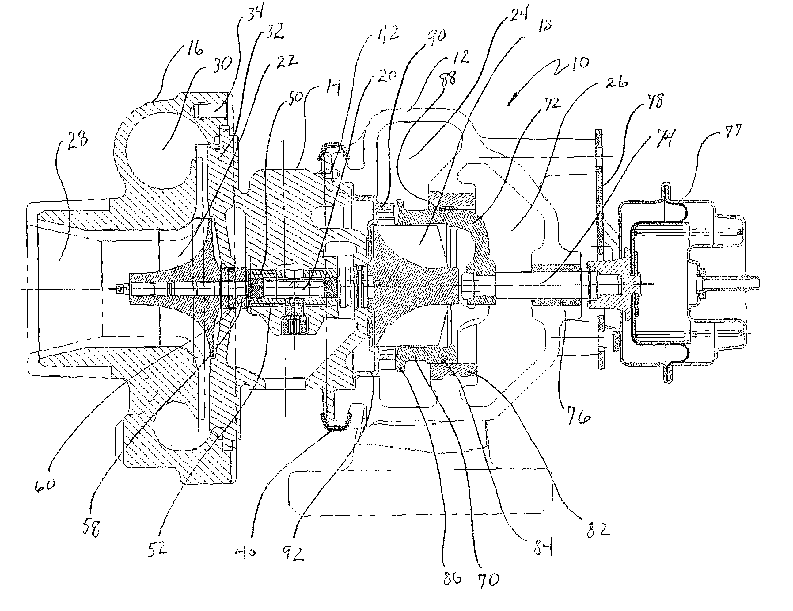
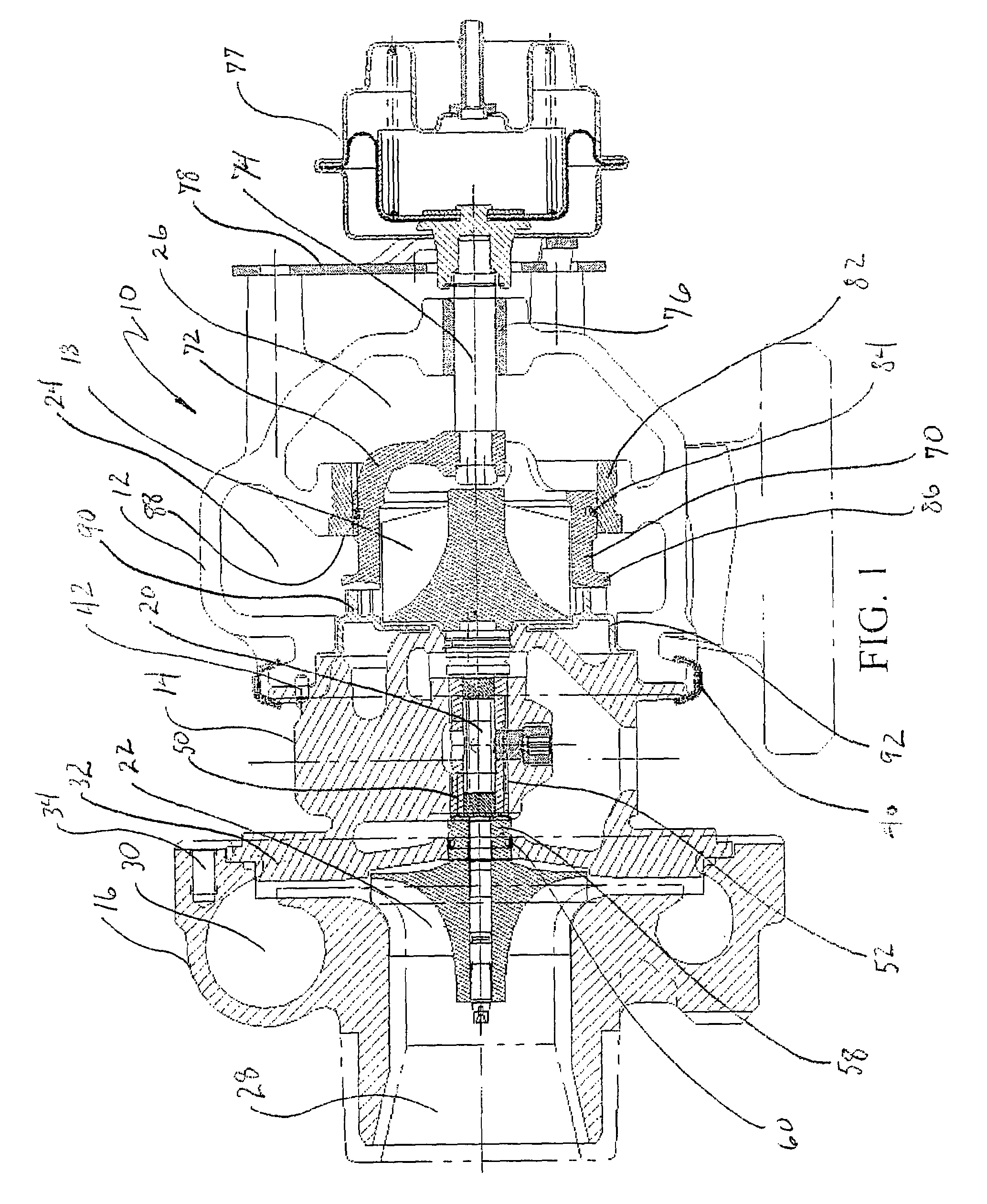
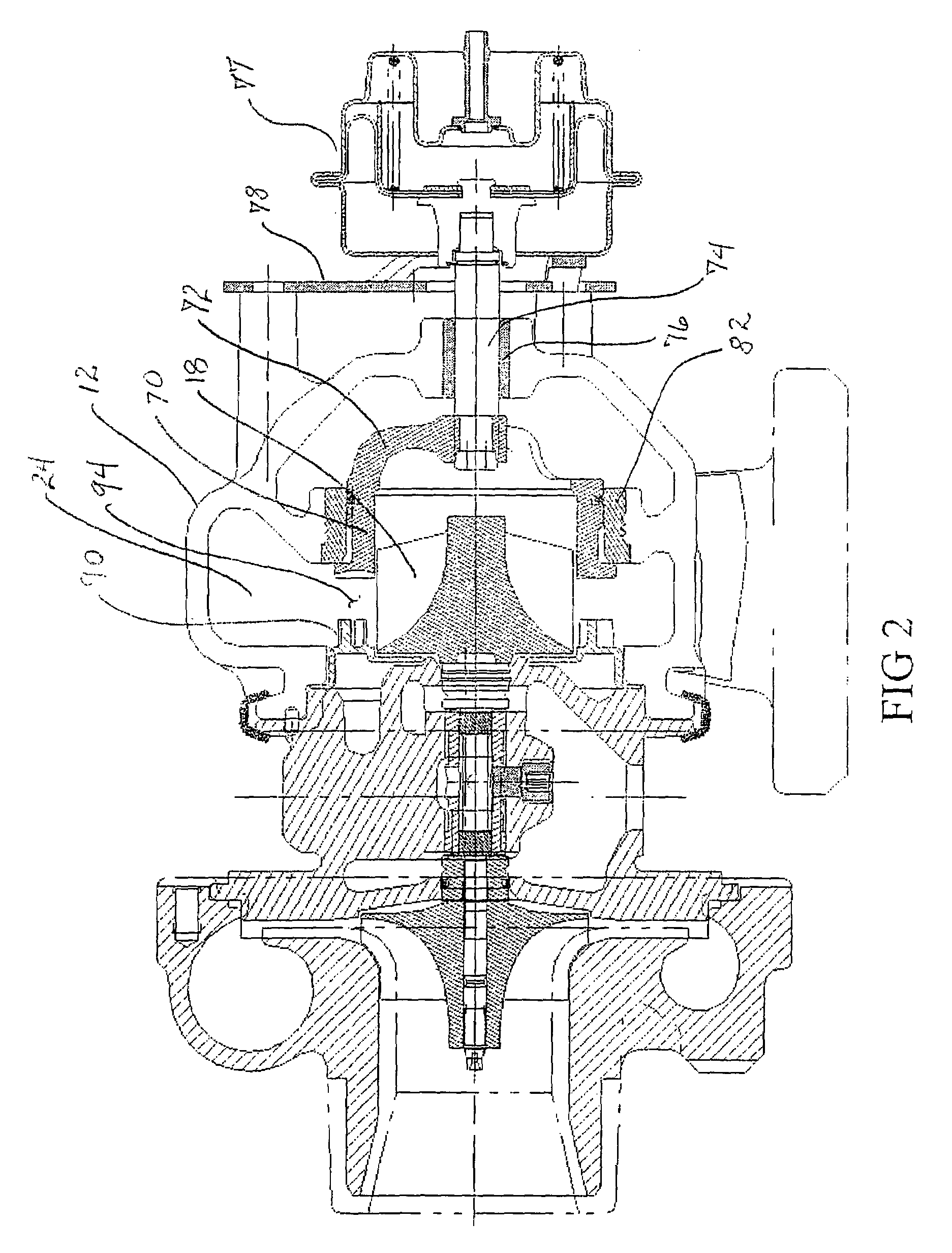
[0013]Referring to the drawings, FIG. 1 shows an embodiment of the invention for a turbocharger 10 which incorporates a turbine housing 12, a center housing 14 and a compressor housing 16. Turbine wheel 18 is connected through shaft 20 to compressor wheel 22. The turbine wheel converts energy from the exhaust gas of an internal combustion engine provided from an exhaust manifold (not shown) to a volute 24 in the turbine housing. The exhaust gas is expanded through the turbine and exits the turbine housing through outlet 26.

[0014]The compressor housing incorporates an inlet 28 and an outlet volute 30. A backplate 32 is connected by bolts 34 to the compressor housing. The backplate is, in turn, secured to the center housing using bolts (not shown) or cast as an integral portion of the center housing. A V-band clamp 40 and alignment pins 42 connect the turbine housing to the center housing.

[0015]A bearing 50 mounted in the shaft bore 52 of the center housing rotationally support the sh...


PUM


Abstract

A turbocharger having a variable geometry turbine inlet incorporates a piston movable to vary the area of the inlet nozzle into the turbine. Vanes extending from the heat shield for flow control in the nozzle are engaged by the piston in a first closed position. In a second open position, the piston is spaced from the vanes increasing the inlet nozzle area.

Description

BACKGROUND OF THE INVENTION[0001]1. Field of the Invention[0002]The present invention relates generally to variable geometry turbochargers. More particularly, a turbocharger is provided having a sliding piston creating a variable nozzle turbine inlet with vanes extending across the nozzle in a closed position of the piston.[0003]2. Description of the Related Art[0004]High efficiency turbochargers employ variable geometry systems for turbine nozzle inlets to increase performance and aerodynamic efficiency. Variable geometry systems for turbochargers have typically been of two types; rotating vane and piston. The rotating vane type exemplified by U.S. Pat. No. 5,947,681 entitled PRESSURE BALANCED DUAL AXLE VARIABLE NOZZLE TURBOCHARGER provide a plurality of individual vanes placed in the turbine inlet nozzle which are rotatable to decrease or increase nozzle area and flow volume. The piston type, which is exemplified by U.S. Pat. Nos. 5,214,920 and 5,231,831 both entitled TURBOCHARGER...

Claims


Application Information

Patent Timeline
IPC IPC(8): F02D23/00F01D17/14F04B17/00F02B37/22F01D17/16F04D25/04
CPCF01D17/143F04D25/04F05D2220/40F02B37/22
Inventor PERRIN, JEAN-LUC HUBERTESPASA, OLIVIERRUFFINONI, MARYLENELOMBARD, ALAINMULLER, PHILIPPE JOSEPH
Owner HONEYWELL GARRETT
Why Eureka
Try Eureka