
Modular fence

Inactive Publication Date: 2006-04-11
ALAN QING LIN ZHU
View PDF15 Cites 38 Cited by
  • Summary
  • Abstract
  • Description
  • Claims
  • Application Information

AI Technical Summary

Benefits of technology

[0023]It is an additional object of the present invention to provide a modular picket fence in the form that may be readily assembled from a set of modular components by a person or homeowner of ordinary skill and experience without the use of welding equipment or other special tools.

Problems solved by technology

The iron fences are sturdy but have a number of problems such as the welded areas are susceptible to rusting even when painted and if galvanized components are used the welding destroys the coating at the welded area that leads to rust.
The wrought iron fences are usually assembled and joined together at the job site and require considerable skill and time on the part of the professional artisans.
For this reason, they are relatively expensive.
However, each bolts and nuts set (40, 42 and 44) must be separately and individually fastened, which is very laborious and time consuming.

Method used


Image

  • Modular fence
  • Modular fence
  • Modular fence

Examples


Embodiment Construction

[0049]Although specific embodiments of the present invention will now be described with reference to the drawings, it should be understood that such embodiments are by way of example only and merely illustrative of but a small number of the many possible specific embodiments which can represent applications of the principles of the present invention. Various changes and modifications obvious to one skilled in the art to which the present invention pertains are deemed to be within the spirit, scope and contemplation of the present invention as further defined in the appended claims.

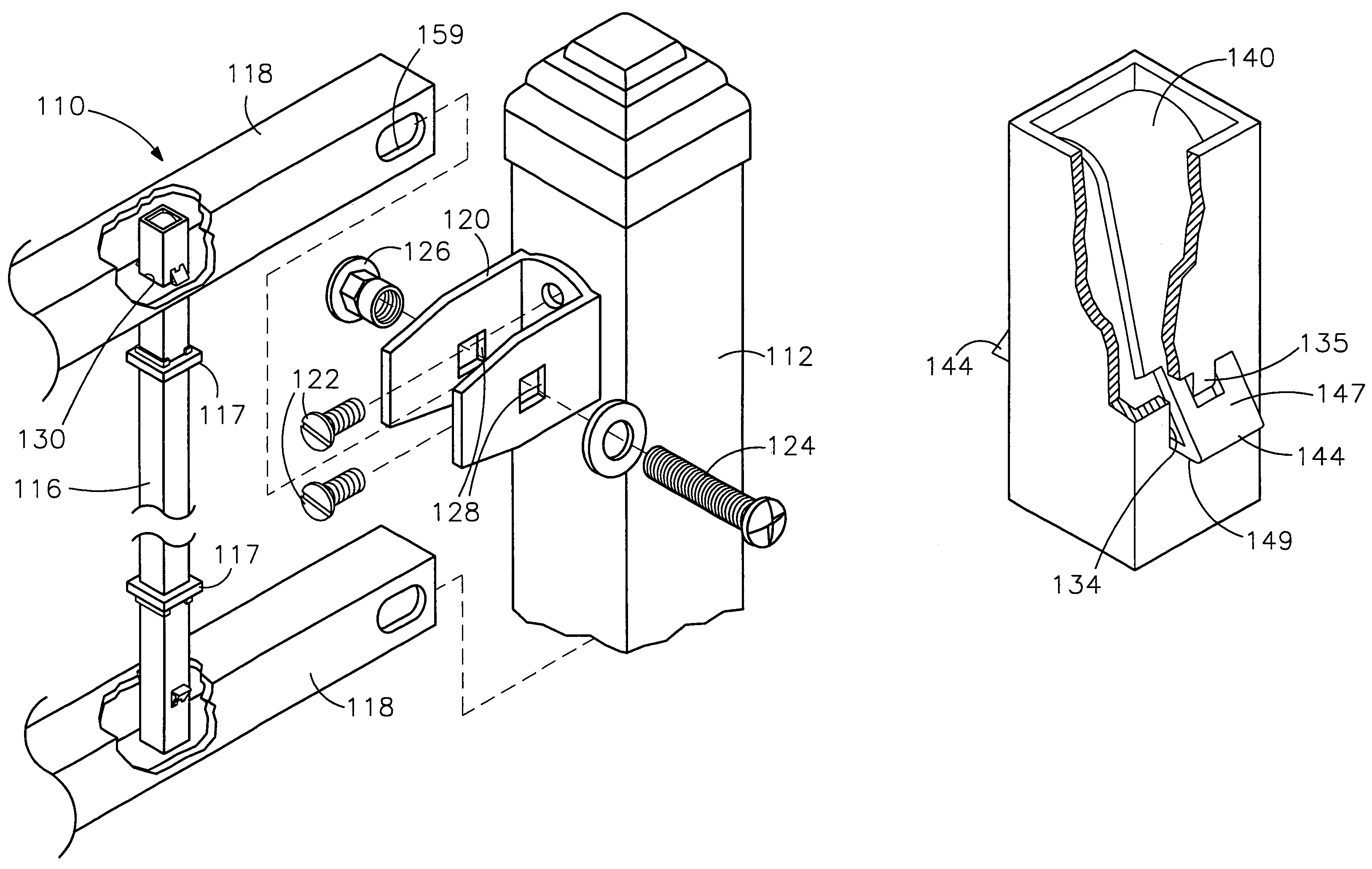
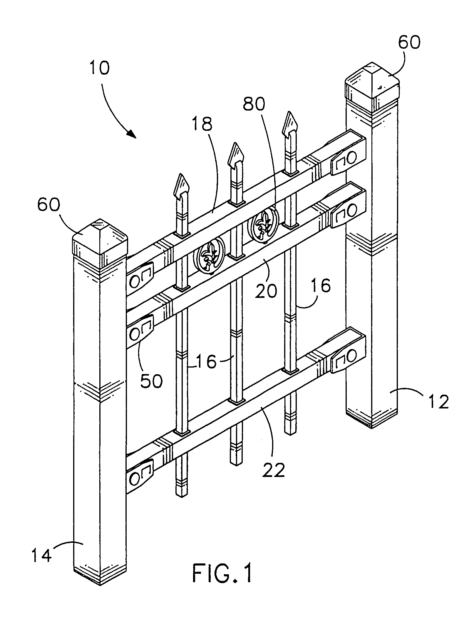
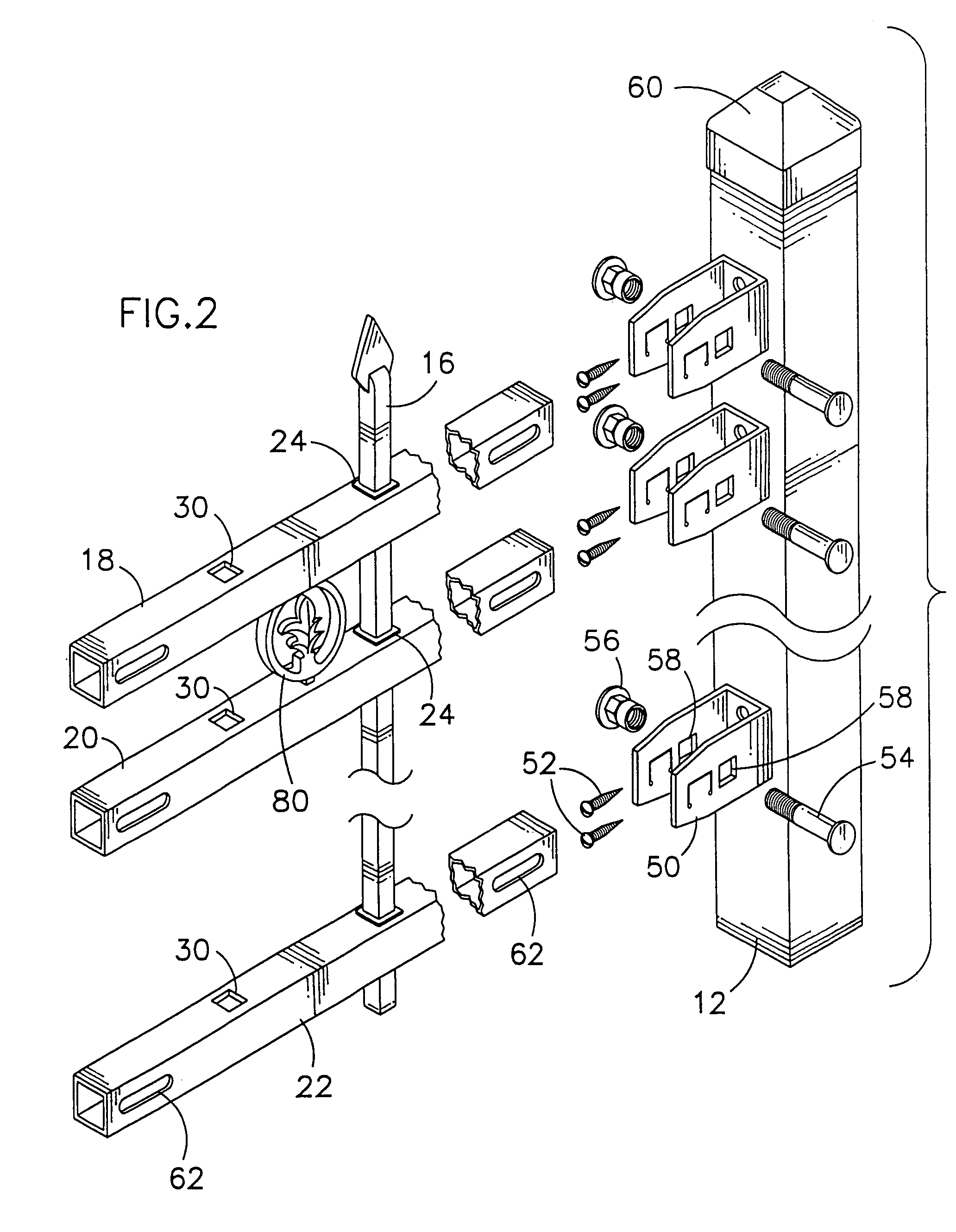
[0050]Described briefly, the present invention is a modular picket fence. In the first arrangement of the present invention, the modular picket fence may be assembled with a pair of horizontal upper rails and one horizontal lower rail as shown in FIGS. 1, 2, 6(f), and 6(g). In the second arrangement of the present invention, the modular picket fence may be assembled with at least one horizontal upper rail ...


PUM


Abstract

A modular picket fence including a pair of vertical separated posts and adapted to be secured to a suitable support surface. A pair of horizontal upper and lower rails extend between and secured to the vertical posts. The upper rail has a plurality of apertures which are aligned with a plurality of apertures on the lower rail. A plurality of vertical pickets are respectively inserted through into aligned apertures of the upper and lower rails. The end portion of each vertical picket has two transverse apertures. A locking member is assembled inside each end portion of the vertical picket. The locking member has spring biased stoppers extending through the transverse apertures at the end portion of the vertical picket, and further extending into and engaging inside the horizontal rail when the end portion of the vertical picket is inserted into one of the apertures of the horizontal rail.

Description

[0001]This Patent Application is a continuation in-part of patent application Ser. No. 10 / 087,258 filed on Mar. 1, 2002, now U.S. Pat No. 6,648,304.BACKGROUND OF THE INVENTION[0002]1. Field of the Invention[0003]The present invention relates generally to the field of fences. More particularly, the present invention relates to the field of modular picket fences.[0004]2. Description of the Prior Art[0005]Specifically, prior art wrought iron fences are well known in the art. These prior art wrought iron fences have become especially popular in recent years as protective fencing around swimming pools, gardens and serve as security barriers around patios and entryways. The wrought iron fences are formed from rods or tubes of metal which are welded to upper and lower rails to form panels or sections. The panels are either welded between upright metal posts or bolted to the upright posts. The iron fences are sturdy but have a number of problems such as the welded areas are susceptible to r...

Claims


Application Information

Patent Timeline
IPC IPC(8): E04H17/14
CPCE04H17/1439E04H17/1443Y10T403/4662Y10T403/4697Y10T403/606F16B2200/20F16B2200/40E04H17/1447E04H17/1488
Inventor ZHU, ALAN QING
Owner ALAN QING LIN ZHU
Learn More