Apparatus and method for transporting water with liner

a technology of ditch liner and apparatus, applied in the field of ditch liner system, can solve the problems of water, metal liners, water loss, and significant quantities of ever more precious commodity, and achieve the effects of avoiding water loss, facilitating assembly of ditch liner sections, and efficient transportation of water

Inactive Publication Date: 2006-04-11
AMERICAN LEAK DETECTION IRRIGATION INC
View PDF8 Cites 20 Cited by
  • Summary
  • Abstract
  • Description
  • Claims
  • Application Information

AI Technical Summary

Benefits of technology

[0012]The present invention provides numerous advantages in connection with an apparatus and method for transporting water through an earthen ditch. At least one advantage of the present invention is that it provides an apparatus and method for lining ditches that is manufactured and constructed of materials that are environmentally safe, non-toxic, and completely recyclable.
[0013]Yet another advantage of the present invention is a unique feature that allows liner sections to be snapped together for assembly into a ditch liner system. Any number of various and varying liner sections formed with locking channel segments in accordance with the present invention may be assembled into a system for transporting water through a ditch. The handle assemblies also facilitate ease of assembly of ditch liner sections while on the bank of a ditch, rather than in the ditch. When snapped together, the ditch liner sections are removably locked together and will remain detachably interconnected until snapped apart or unlocked. Snapped together locking channel segments, in accordance with the present invention, form a substantially water tight seal between locking channel segments. Snapped together locking channel segments therefore substantially eliminate loss of water through seepage and similar causes of water losses.
[0014]The advantages obtained because of the capability of snapping together and snapping apart a number of ditch liner sections also permit assembly of a series of interconnected ditch liner sections before installation of an assembled ditch liner assembly in a ditch. As used in this document, the terms “ditch liner section,”“liner section,”“liner,” and “section” mean, without limitation, the components described in this document that may be removably connected to form the apparatus, method and system for transporting water in accordance with the present invention. The terms therefore include a ditch liner section, an inlet / outlet box or channel, a diversion section, an adaptor, and a splitter section as described and claimed in this document.
[0015]Another advantage of the present invention is its ability to transport water efficiently and at larger than customary flow rates, while reducing ditch insiltation, cleaning and maintenance, while significantly reducing water loss.
[0016]Yet another advantage of the present invention is its capability to withstand climate and temperature changes, as well as puncture shear from domestic and wild animals.
[0017]Still another advantage of the present invention is its low cost of installation, particularly in comparison with traditional materials used to line earthen ditches such as concrete, metal, and PVC materials.

Problems solved by technology

During transportation of water through earthen ditches unlined by a material other than dirt, significant quantities of that ever more precious commodity, water, are lost because of seepage, erosion, trans-evaporation and other causes.
Concrete, however, is expensive to install, is substantially permanent, and requires erection of forms into which concrete must be formed to create necessary shapes.
Metal liners, however, have proven too rigid, too heavy to install easily, and unacceptable for a variety of environmental reasons.
Additional limitations of those prior approaches to transporting water through earthen ditches are significant.
Repair and maintenance of ditches is costly and labor intensive.
Limitations of prior approaches that involved lining earthen ditches with a variety of materials such as concrete, metal and more recently one or more forms of polyvinyl chloride materials, are expensive and unresponsive to modern environmental concerns.
Such materials have proven difficult to install in remote geographical areas, inflexibly positioned once installed, and often require major construction efforts often neither practical nor affordable.
Such materials also do not allow making component ditch parts that snap together to form a detachable but locked joint.
Inability to readily direct and redirect water flow to other ditches or in other directions using concrete or steel also is a significant limitation on their use.

Method used


Image

  • Apparatus and method for transporting water with liner
  • Apparatus and method for transporting water with liner
  • Apparatus and method for transporting water with liner

Examples


Embodiment Construction

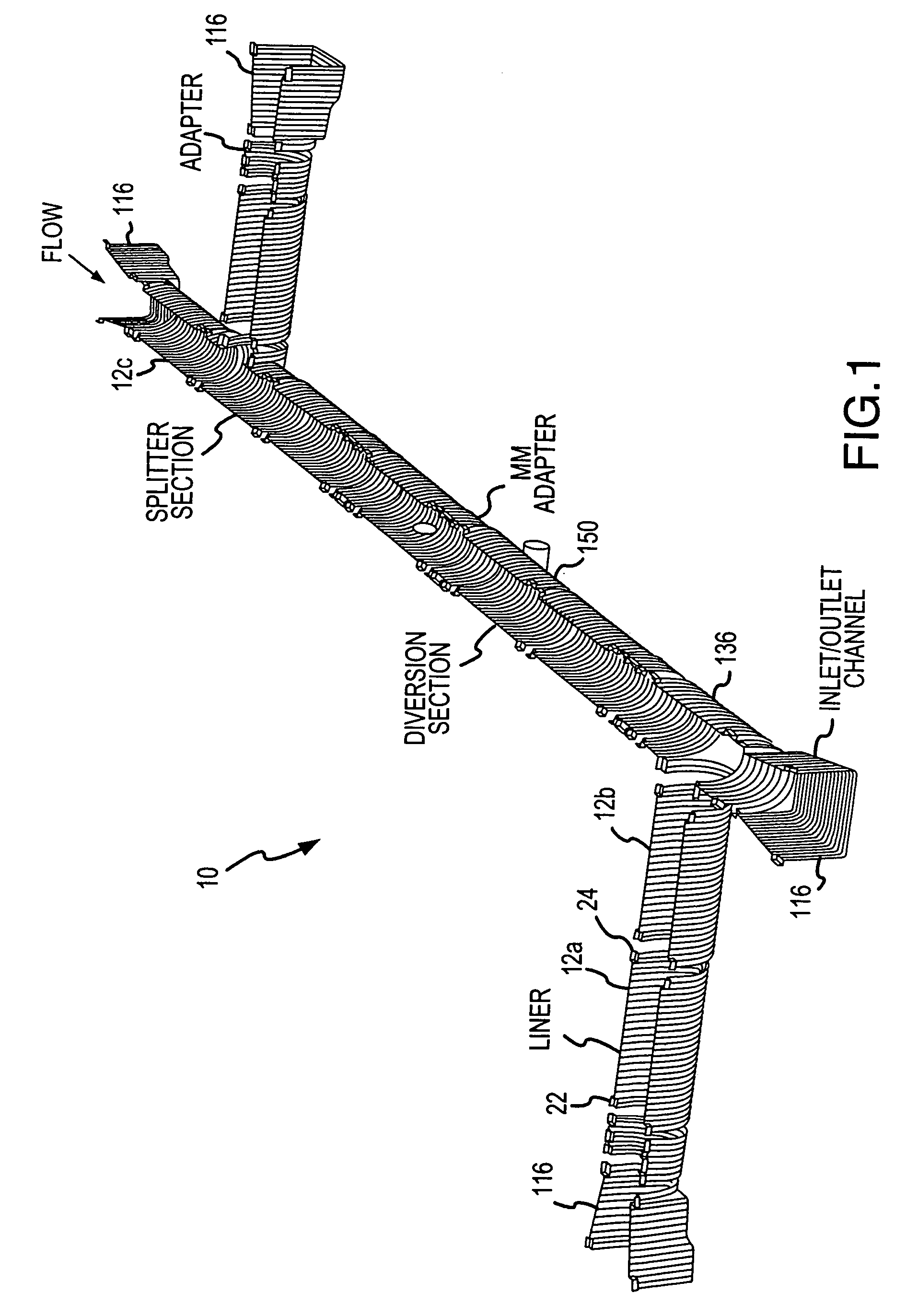
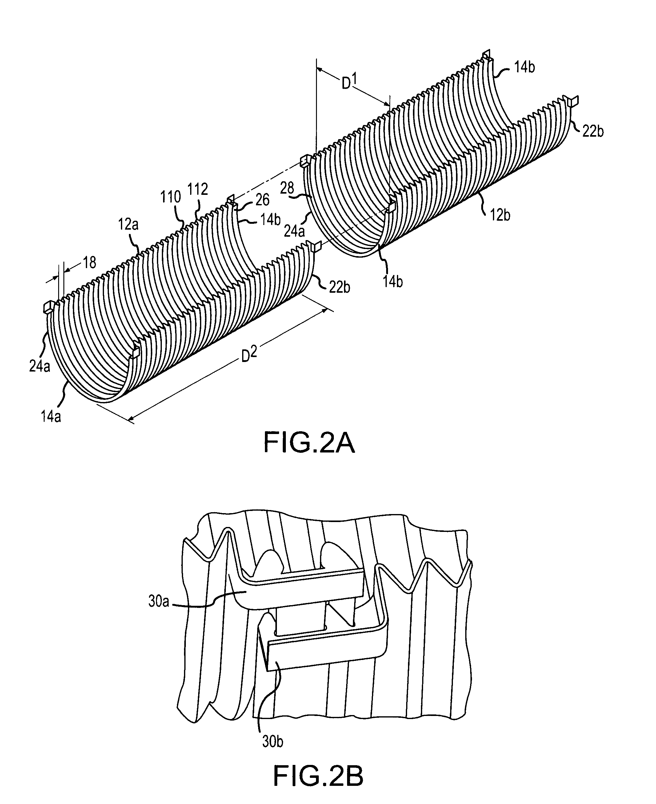
[0062]Briefly, the present invention provides an apparatus and method for lining ditches. In a preferred embodiment of the present invention, the apparatus and method for lining ditches includes a plurality of substantially corrugated ditch liner sections that are substantially semi-cylindrical in shape. In a preferred embodiment of the present invention, the plurality of substantially corrugated ditch liner sections are made of polyethylene. The plurality of ditch liner sections are designed to be assembled by snapping together opposing ends of the ditch liner sections. Snapping together the ditch liner sections results in a detachably locked together series of liner sections. A sealant that does not bond with the ditch liner sections may also be included.

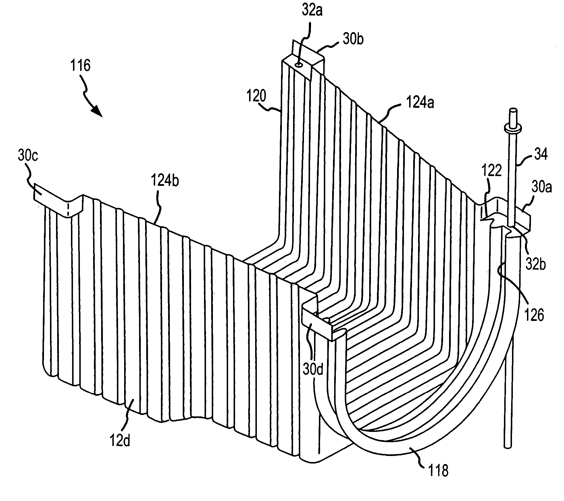
[0063]In a preferred embodiment of the present invention, an inlet / outlet channel is included. The inlet / outlet channel is detachably and removably engageable with at least one end of a ditch liner section. The inlet / outlet channe...


PUM


Abstract

An apparatus and method for lining ditches is provided. The apparatus and method for lining ditches, according to the present invention, includes a plurality of substantially corrugated liner sections, preferably made of a thermoplastic material such as polyethylene. Each liner section is designed to be assembled by detachably engaging ends of ditch liner sections. A sealant that does not bond with the material from which the liner sections are made may also be included. An inlet / outlet channel is included. The inlet / outlet channel is removably connectable with at least one end of a liner section by snapping together the two components. A liner section in the form of a splitter section also is provided. A splitter section permits rerouting the flow of water in a variety of directions through a ditch lined with the apparatus of the present invention. Also, a diverter section is included for diverting water from one flow direction through the ditch to a point or area of application of water. In addition, an adaptor also is included. An adaptor may be used to interconnect incompatible liner sections.

Description

CROSS-REFERENCE TO RELATED APPLICATION[0001]This application is a divisional application of U.S. application Ser. No. 10 / 316,756 filed on Dec. 11, 2002, for which U.S. Pat. No. 6,692,186 B1 issued on Feb. 17, 2004.FIELD OF THE INVENTION[0002]The present invention pertains generally to transportation of water. More particularly, the new and useful invention claimed in this document pertains to a ditch liner system for conveying water through earthen irrigation ditches. The present invention is particularly, but not exclusively, useful for providing both an apparatus and method for detachably connecting liner sections by snapping liner section ends together to secure individual sections to form a ditch liner system within a ditch. The present invention also is useful for directing water flow into, among, and from interconnected ditch liner sections and ditches in such a way as to reduce water loss during transportation of water through the system of ditch liners practiced in accordanc...

Claims


Application Information

Patent Timeline
Patent Type & Authority Patents(United States)
IPC IPC(8): E02B5/00E02B13/00E02B5/02
CPCE02B13/00E02B5/02
Inventor SUAZO, KENNETH L.SUAZO, ISAACSUAZO, ANNABELLEDAUGHERTY, DAWN SUAZOGRIEGO, JUANSUAZO, JULIAN
Owner AMERICAN LEAK DETECTION IRRIGATION INC
Why Eureka
Try Eureka