Sample processing devices

a processing device and sample technology, applied in the direction of optical light guides, charge supports, fluid speed measurement, etc., can solve the problems of several temperature control related problems, time-consuming and expensive individual processing, and significant adverse effects on the reaction

Inactive Publication Date: 2006-04-11
3M INNOVATIVE PROPERTIES CO
View PDF82 Cites 133 Cited by
  • Summary
  • Abstract
  • Description
  • Claims
  • Application Information

AI Technical Summary

Benefits of technology

[0016]Yet another advantage of the present invention is that the devices may be mass manufactured in a web-based manufacturing process in which the various components may be continuously formed and / or bonded, with the individual devices being separated from the continuous web.
[0017]As used in connection with the present invention, the following terms shall have the meanings set forth below.
[0018]“Deformable seal” (and variations thereof) means a seal that is permanently deformable under mechanical pressure (with or without a tool) to occlude a conduit along which the deformable seal is located.
[0019]“Thermal processing” (and variations thereof) means controlling (e.g., maintaining, raising, or lowering) the temperature of sample materials to obtain desired reactions. As one form of thermal processing, “thermal cycling” (and variations thereof) means sequentially changing the temperature of sample materials between two or more temperature setpoints to obtain desired reactions. Thermal cycling may involve, e.g., cycling between lower and upper temperatures, cycling between lower, upper, and at least one intermediate temperature, etc.
[0020]In one aspect, the invention provides a device for use in processing sample materials, the device including a body that includes a first side attached to a second side; a process array formed between the first and second sides, the process array including a loading structure, a main conduit with a length, a plurality of process chambers distributed along the main conduit, wherein the loading structure is in fluid communication with the plurality of process chambers through the main conduit; and a deformable seal located between the loading structure and the plurality of process chambers.
[0021]In another aspect, the present invention provides a device for use in processing sample materials, the device including a body that includes a first side attached to a second side; a process array formed between the first and second sides, the process array including a loading structure, a main conduit with a length, a plurality of process chambers distributed along the main conduit, wherein the loading structure is in fluid communication with the plurality of process chambers through the main conduit; and a deformable seal located between the loading structure and the plurality of process chambers, wherein the deformable seal includes a deformable metallic layer forming a portion of the second side of the body and adhesive located between the first side and the second side, the adhesive extending along substantially all of the length of the main conduit, wherein closure of the deformable seal is effected by adhering the first side and the second side together using the adhesive within the main conduit.

Problems solved by technology

In many such reactions, a temperature variation of even 1 or 2 degrees Celsius may have a significantly adverse impact on the reaction.
Although it may be possible to process samples individually and obtain accurate sample-to-sample results, individual processing can be time-consuming and expensive.
However, this approach presents several temperature control related issues.
When using multiple chambers, the temperature uniformity from chamber to chamber may be difficult to control.
Another problem involves the speed or rate at which temperature transitions occur when thermal processing, such as when thermal cycling.
Still another problem is the overall length of time required to thermal cycle a sample(s).
However, the distribution system presents the potential for cross-contamination.
Sample may inadvertently flow among the chambers during processing, thereby potentially adversely impacting the reaction(s) occurring in the chambers.
This may be particularly significant when multiple samples are being processed.
In addition, the distribution system may present problems when smaller than usual samples are available, because the distribution system is in fluid communication with all of the process chambers.
As a result, it is typically not possible to prevent delivery of sample materials to all of the process chambers to adapt to the smaller volume samples.
Thermal processing, in and of itself, presents an issue in that the materials used in the devices may need to be robust enough to withstand repeated temperature cycles during, e.g., thermal cycling processes such as PCR.

Method used


Image

  • Sample processing devices
  • Sample processing devices
  • Sample processing devices

Examples


Embodiment Construction

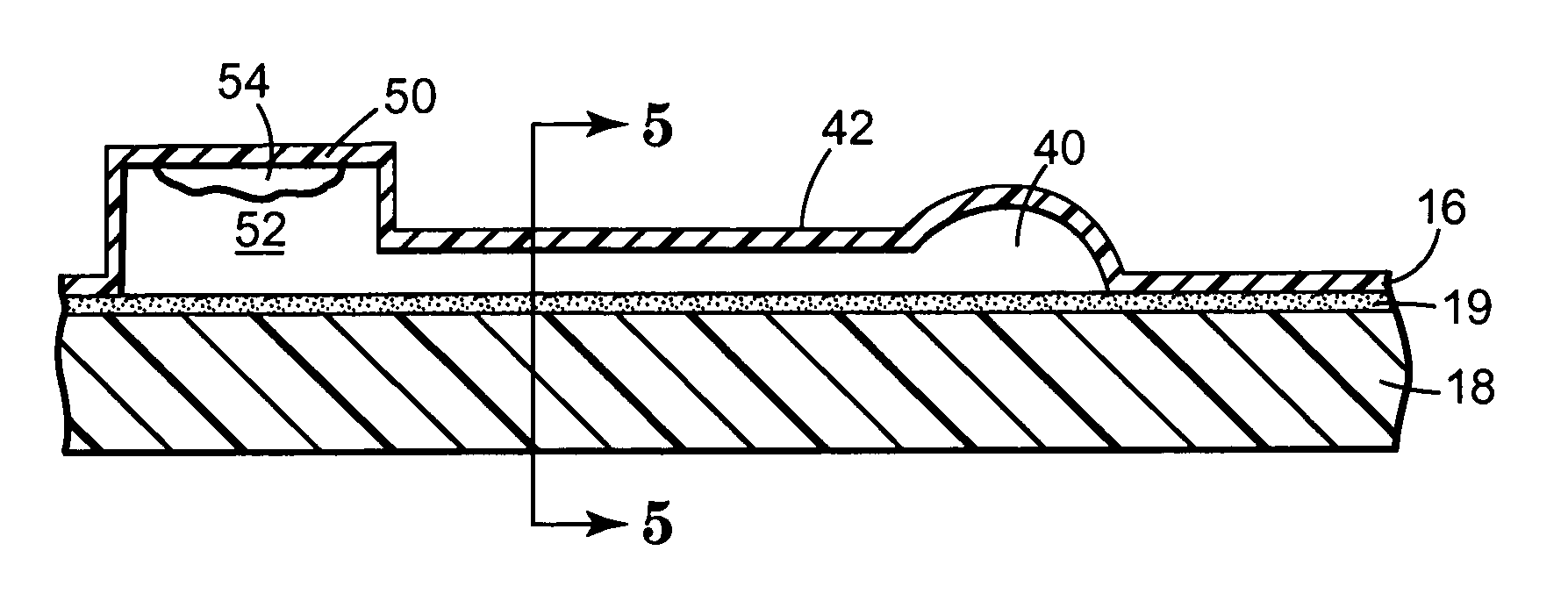
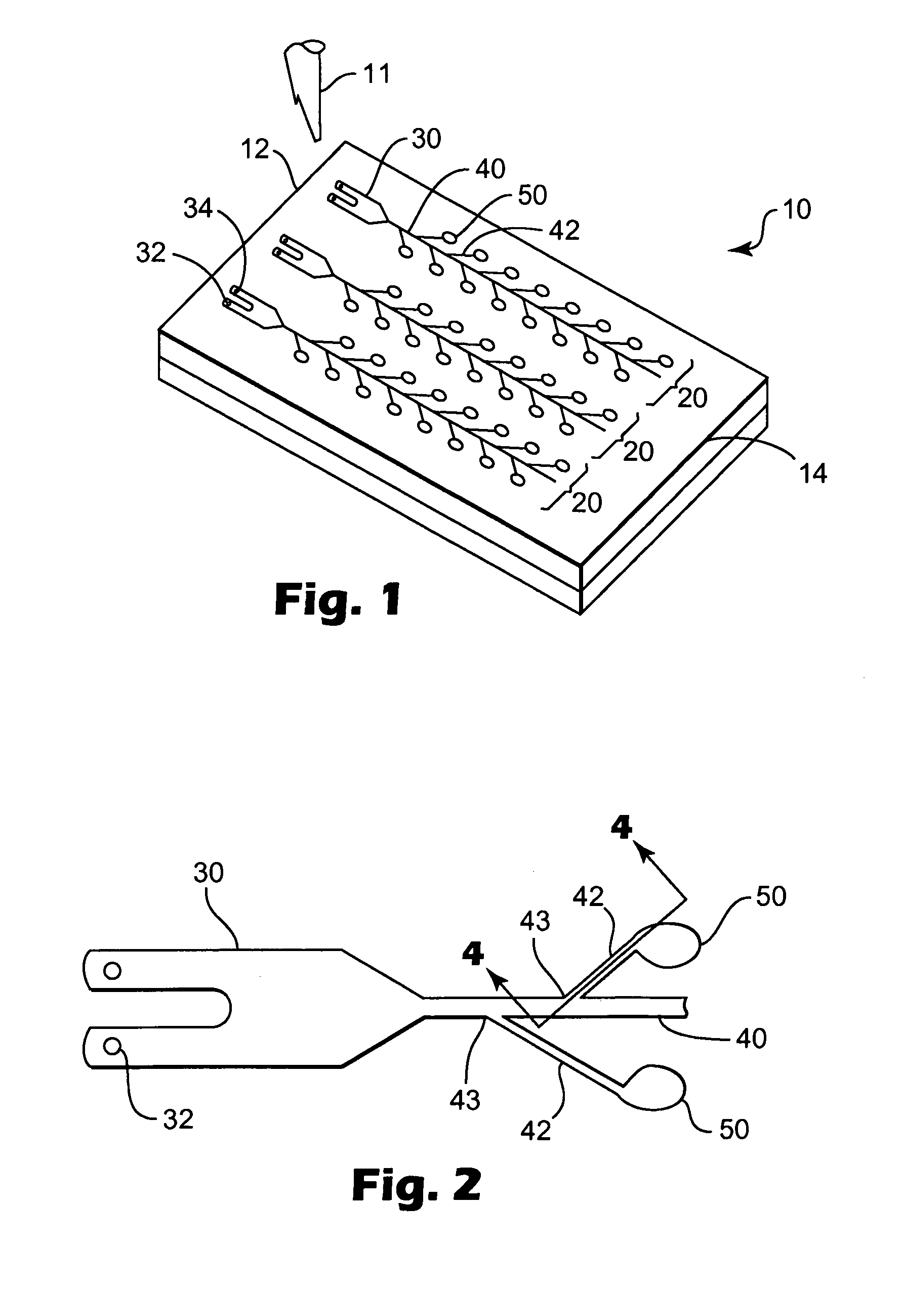
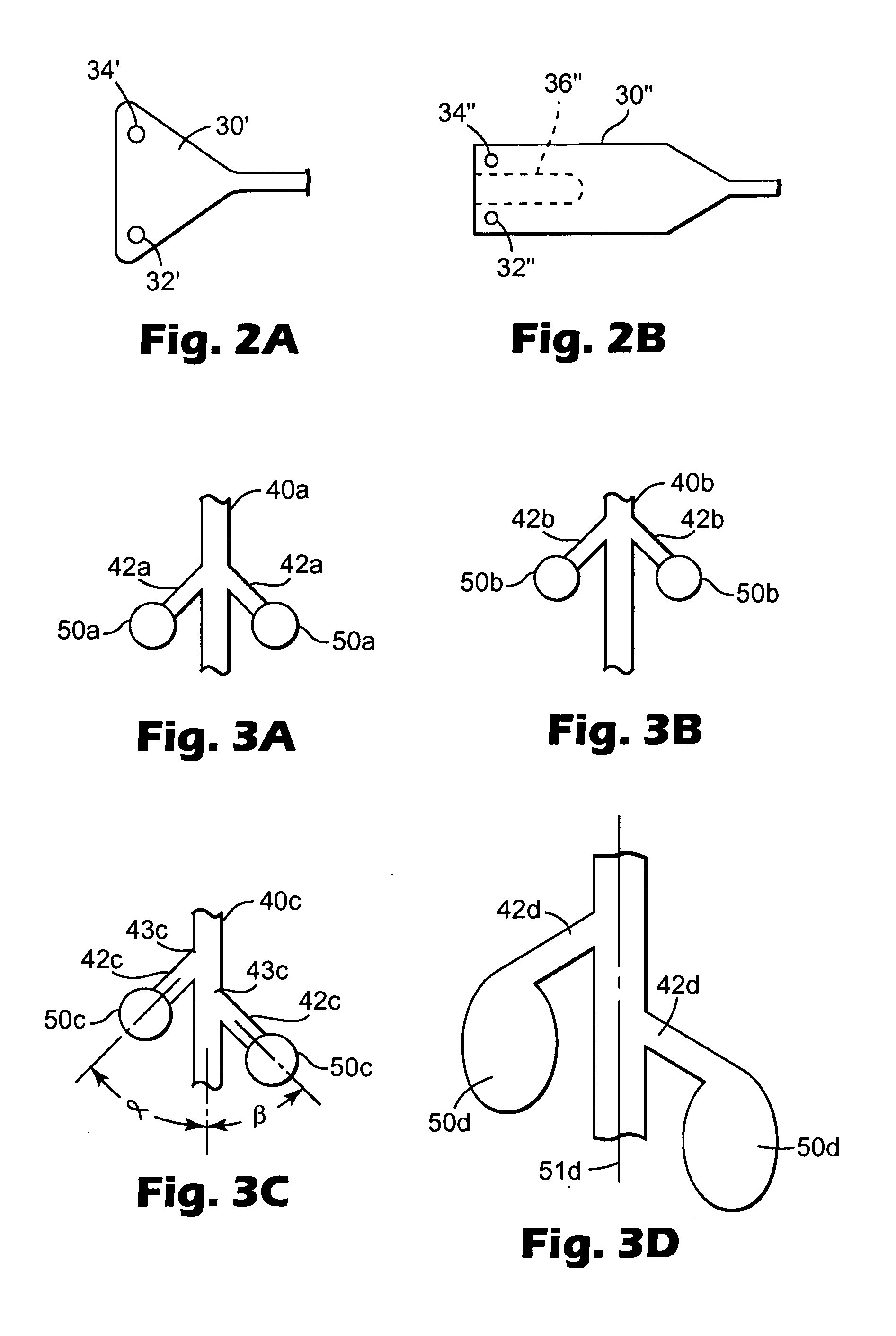
[0065]The present invention provides a sample processing device that can be used in the processing of liquid sample materials (or sample materials entrained in a liquid) in multiple process chambers to obtain desired reactions, e.g., PCR amplification, ligase chain reaction (LCR), self-sustaining sequence replication, enzyme kinetic studies, homogeneous ligand binding assays, and other chemical, biochemical, or other reactions that may, e.g., require precise and / or rapid thermal variations. More particularly, the present invention provides sample processing devices that include one or more process arrays, each of which include a loading chamber, a plurality of process chambers and a main conduit placing the process chambers in fluid communication with the loading chamber.

[0066]Although various constructions of illustrative embodiments are described below, sample processing devices of the present invention may be manufactured according to the principles described in U.S. Provisional ...


PUM

PropertyMeasurementUnit
temperatureaaaaaaaaaa
anglesaaaaaaaaaa

Abstract

Methods and devices for thermal processing of multiple samples at the same time are disclosed. The sample processing devices provide process arrays that include conduits useful in distributing sample materials to a group pf process chambers located in fluid communication with the main conduits. The sample processing devices may include one or more of the following features in various combinations: deformable seals, process chambers connected to the main conduit by feeder conduits exiting the main conduit at offset locations, U-shaped loading chambers, and a combination of melt bonded and adhesively bonded areas.

Description

RELATED APPLICATIONS[0001]This application claims the benefit of U.S. Provisional Patent Application Ser. No. 60 / 214,508 filed on Jun. 28, 2000 and titled THERMAL PROCESSING DEVICES AND METHODS, which is hereby incorporated by reference in its entirety.[0002]This application is a continuation-in-part of U.S. patent application Ser. No. 09 / 710,184, filed Nov. 10, 2000, titled CENTRIFUGAL FILLING OF SAMPLE PROCESSING DEVICES (now issued as U.S. Pat. No. 6,627,159), which is hereby incorporated by reference in its entirety.GRANT INFORMATION[0003]The present invention may have been made with support from the U.S. Government under NIST Grant No. 70NANB8H4002. The U.S. Government may have certain rights in the inventions recited herein.FIELD OF THE INVENTION[0004]The present invention relates to the field of sample processing devices. More particularly, the present invention relates to sample processing devices and methods of manufacturing and using the sample processing devices.BACKGROUN...

Claims


Application Information

Patent Timeline
Patent Type & Authority Patents(United States)
IPC IPC(8): G01N1/00B01L3/00G01N1/10G01N15/06G01N21/00B01J19/00B01L7/00B01L9/00B81B1/00C12M1/00F27B9/16F27D5/00G01N1/28G01N35/00G01N37/00
CPCB01L3/5025B01L3/502707B01L3/502738B01L7/52B01L7/525B01L9/527G01N35/00069B01L3/50255Y10T436/25B01L2200/0642B01L2200/0689B01L2200/142B01L2300/0654B01L2300/0816B01L2300/0864B01L2300/0887B01L2400/0406B01L2400/0409B01L2400/0481B01L2400/0655B01L2400/0661F27B9/16F27D5/00Y10T436/2575
Inventor BEDINGHAM, WILLIAMAYSTA, JAMES E.ROBOLE, BARRY W.WOOD, KENNETH B.
Owner 3M INNOVATIVE PROPERTIES CO
Why Eureka
Try Eureka