Thermal protector

a technology of thermal protector and shielding plate, which is applied in the direction of protective switch details, protective switch operating/releasing mechanism, and relay, etc., can solve the problems of short circuit and thermal protector as above described conventional technique, and achieve the effect of improving the reliability of the appliance, enhancing the degree of freedom of appliance design, and eliminating restrictions on the arrangement position of thermal protector

Inactive Publication Date: 2006-04-11
UCHIYA THERMOSTAT
View PDF20 Cites 19 Cited by
  • Summary
  • Abstract
  • Description
  • Claims
  • Application Information

AI Technical Summary

Benefits of technology

[0017]As described above, according to the present invention, a problem that a conductive member in the periphery of contacts is extraordinarily heated and melted by a spattering arc, which hastens damage or causes a short circuit is solved. As a result, the reliability of an appliance is improved. Furthermore, the thermal protector is configured to make it difficult that a wind directly flows between the contacts in any direction, whereby restrictions on an arrangement position of the thermal protector are eliminated, which enhances the degree of freedom of designing an appliance where the thermal protector is arranged inside, and offers a convenience.

Problems solved by technology

The thermal protector as the above described conventional technique has one problem.
However, if the wind velocity exceeds a limit, an arc comes out of the contacts and is spattered to a peripheral conductive member in many cases.
If a conductive member in the periphery of contacts is repeatedly melted, this causes diverse problems such as hastening the wear-out of the conductive member, causing a short circuit, or the like.

Method used


Image

  • Thermal protector
  • Thermal protector
  • Thermal protector

Examples


Embodiment Construction

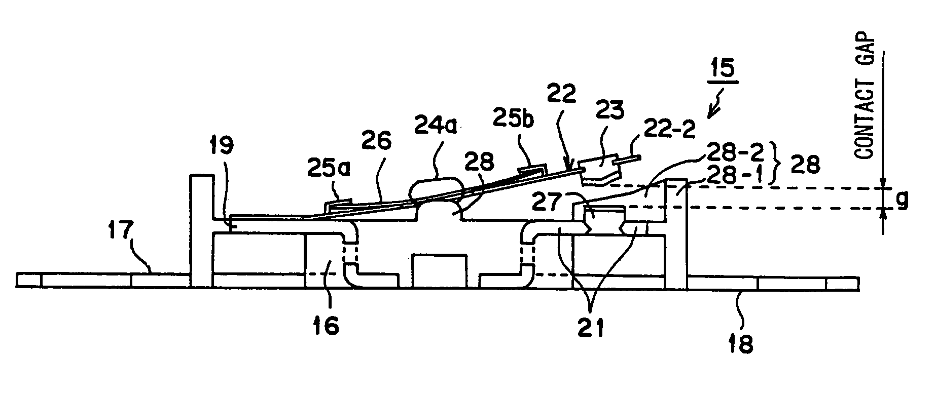
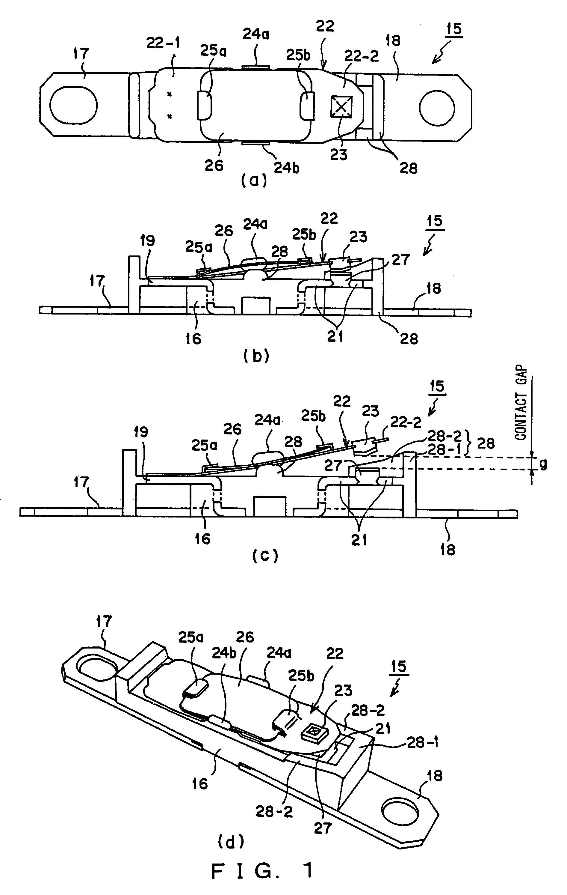
[0025]FIG. 1(a) is a plan view of a thermal protector according to the first preferred embodiment, FIG. 1(b) is a sectional side view showing the configuration where contacts are closed at a normal temperature, FIG. 1(c) is a sectional side view showing the state where the contacts are open when the thermal protector operates at a high temperature, and FIG. 1(d) is a perspective view showing an entire configuration.

[0026]In the thermal protector 15 shown in FIGS. 1(a) to 1(d), configurations of a securing portion 16 made of an insulating synthetic resin, metal external circuit connection terminals 17 and 18, their upper exposed portions 19 and 21, a metal movable plate 22, one end 22-1 of the metal movable plate 22, the other end 22-2 of the metal movable plate 22, a movable contact 23, drop preventing pieces 24a and 24b, engagement pieces 25a and 25b, a bimetal 26, and a fixed contact 27 are similar to those of the securing portion 2, the external circuit connection terminals 3 and...


PUM


Abstract

A thermal protector includes a partition wall which encloses an arrangement portion of a movable contact and a fixed contact from three sides. The partition wall is adjacent the contacts in a range that does not inhibit the opening / closing operations of the contacts, and is formed to be higher than the fixed contact and a gap between the contacts, but not exceed the height of a movable plate to which the movable contact is attached, when the contacts are released.

Description

TECHNICAL FIELD[0001]The present invention relates to a thermal protector used to prevent the overheating of a hot-air generating device of a hair dryer, an electronic fan heater, a popcorn machine, etc.BACKGROUND ART[0002]Conventionally, a thermal protector like that shown in FIG. 4 exists. In the thermal protector 1 shown in this figure, external circuit connection terminals 3 and 4 are respectively secured to both ends of a lower portion of a securing portion 2 made of an insulating synthetic resin. The ends of the external circuit connection terminals 3 and 4, which are secured to the securing portion 2, are incorporated into one body with the securing portion 2 in a form of being folded within the securing portion and respectively exposed at both ends of an upper portion of the securing portion 2, although this is not clearly shown in the figure.[0003]To an upper exposed portion 5 of the external circuit connection terminal 3, one end 6-1 of a movable plate 6 is secured, for ex...

Claims


Application Information

Patent Timeline
Patent Type & Authority Patents(United States)
IPC IPC(8): H01H37/52A45D20/12H01H37/54
CPCH01H37/5418
Inventor TAKEDA, HIDEAKI
Owner UCHIYA THERMOSTAT
Why Eureka
Try Eureka