Communications interface between clock domains with minimal latency

a technology of communication interface and clock domain, applied in the field of communication networks, can solve the problems of cumbersome reconfiguration of ports in the network, complex management of the network, and relatively limited number of ports supportable by conventional switches, and achieve the effect of minimizing the latency of the network switch

Inactive Publication Date: 2006-04-11
TEXAS INSTR INC
View PDF14 Cites 13 Cited by
  • Summary
  • Abstract
  • Description
  • Claims
  • Application Information

AI Technical Summary

Benefits of technology

[0018]It is a further object of the present invention to provide such a circuit and method in which the latency of the network switch is minimized.

Problems solved by technology

Heretofore, the number of ports supportable by conventional switches has been relatively limited.
However, network designers and users are desirous of supporting large numbers of ports, particularly if dedicated full-duplex connections of client workstations (e.g., client workstations C4 through C6 of FIG. 1) are desired.
Not only does the management of the network become complex in such conventional arrangements, but the reconfiguration of ports in the network is made quite cumbersome.
According to conventional realizations, however, dribble-down buffers have necessarily been relatively deep, and thus costly to implement.
Further, the use of a dribble-down buffer generally necessitates a sufficient gap in time between data frames, within which the buffer can be reset.
In any event, dribble-down buffers, and other conventional approaches to problems arising from different receive and transmit frequencies, insert some amount of undesired latency within each switch device.

Method used


Image

  • Communications interface between clock domains with minimal latency
  • Communications interface between clock domains with minimal latency
  • Communications interface between clock domains with minimal latency

Examples


Embodiment Construction

[0031]As will become apparent from the following description, the present invention may be utilized in connection with a wide variety of implementations, and in connection with packet-switched networks of various protocols and communications types. The following description, which is directed to a preferred embodiment of the present invention in connection with Ethernet networks, is therefore presented by way of example only, it being understood that those skilled in the art having reference to this specification will be readily able to utilize and realize the present invention in connection with alternative implementations, for Ethernet and networks of other types, without departing from the scope of the present invention as hereinafter claimed.

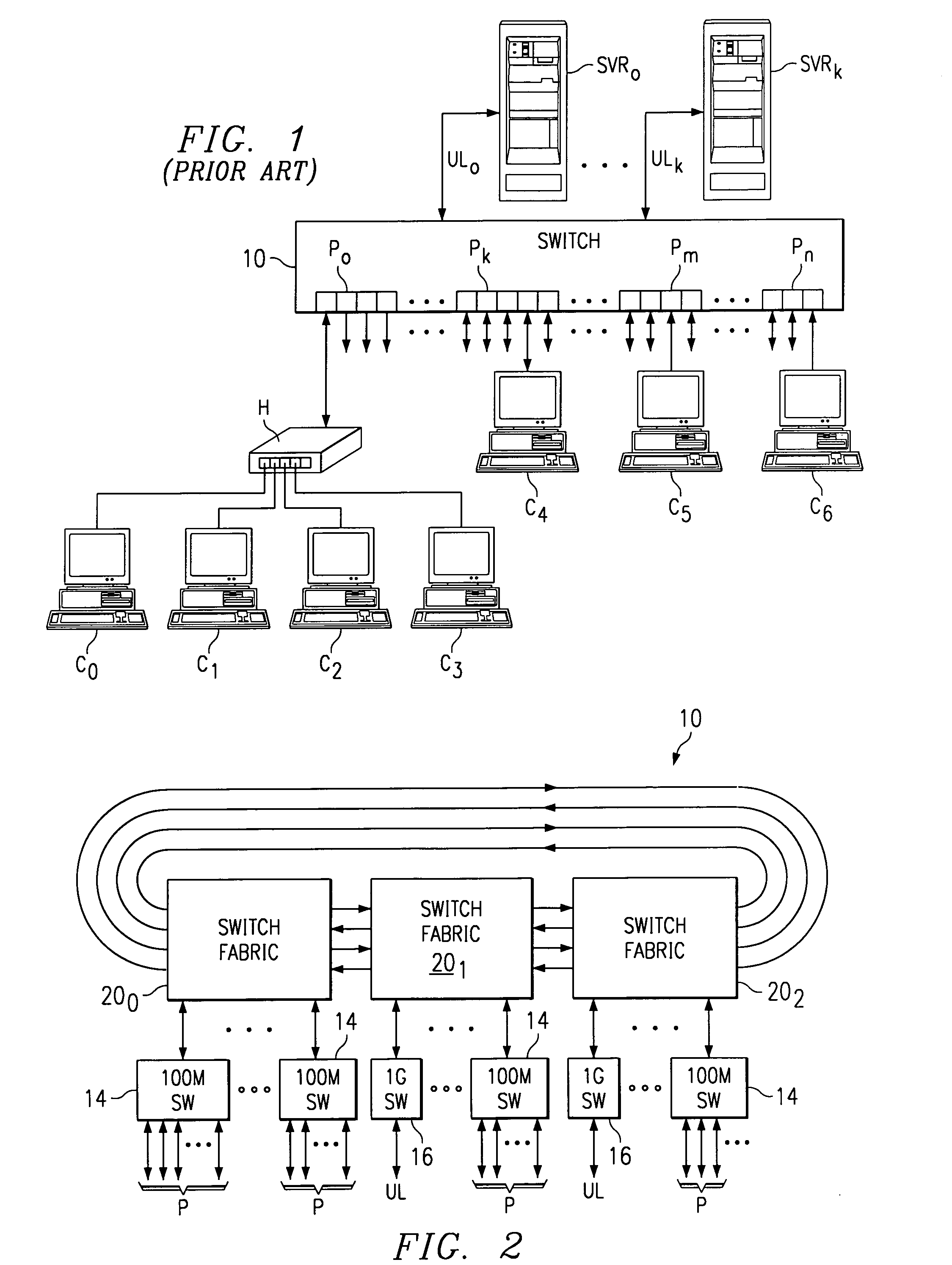
[0032]FIG. 1 is a high-level block diagram of an Ethernet network into which the preferred embodiment of the present invention may be readily implemented. As in the case of the conventional switched network discussed above relative to FIG. 1...


PUM


Abstract

A network switch system (10) is disclosed, in which a plurality of switch fabric devices (20) are interconnected according to a ring arrangement, each of the switch fabric devices (20) including therein switch interfaces (22) coupled to corresponding network switches (14, 16). Each switch fabric device includes a plurality of ring paths (24), each of which is associated with a receive ring interface (26R) and a transmit ring interface (26X). Each ring path (24) includes a circular buffer (44) having a plurality of entries, each of which is associated with valid logic (50). The valid logic (50) for each entry presents valid signals on valid lines (WV, RV) to the receive and transmit domains of the ring path (24), and receives signals on write and read word request lines (WRW, RDW) therefrom. Control of the access to the circular buffer (44) is made according to the write and read word request lines (WRW, RDW) for the corresponding entries of the circular buffer (44) to which write pointers and read pointers point. The write word request line (WRW) sets the valid lines (WV, RV) for the corresponding entry in each of the two clock domains, while the read word request line (RDW) resets these valid lines (WV, RV) for that entry. Differences in clock frequency between the receive and transmit clock domains are thus compensated, with a minimum latency.

Description

[0001]This application claims priority under 35 U.S.C. § 119(e)(1) of provisional application No. 60 / 185,802 filed Feb. 29, 2000.CROSS-REFERENCE TO RELATED APPLICATIONS[0002]Not applicable.STATEMENT REGARDING FEDERALLY SPONSORED RESEARCH OR DEVELOPMENT[0003]Not applicable.BACKGROUND OF THE INVENTION[0004]This invention is in the field of communications networks, and is more specifically directed to the synchronous communication of data among network elements that operate at different clock frequencies.[0005]In recent years, the deployment of local-area networks (LANs) of personal computers and workstations in business and educational enterprises has become widespread. These modem networks have provided significant productivity gains, not only by providing individuals with the ability to electronically communicate with one another, but also by enabling shared access of data bases and documents stored on a central server and on the networked client workstations. With the ever-improvin...

Claims


Application Information

Patent Timeline
Patent Type & Authority Patents(United States)
IPC IPC(8): H04L12/42H04L7/00
CPCH04L7/005H04L7/0012
Inventor ROBERTSON, IAINSZCZEPANEK, ANDREBEAUDOIN, DENIS R.
Owner TEXAS INSTR INC
Why Eureka
Try Eureka