
OFDM signal transmission scheme, and OFDM signal transmitter/receiver

Inactive Publication Date: 2006-04-11
INTERDIGITAL PATENT HLDG INC
View PDF8 Cites 73 Cited by
  • Summary
  • Abstract
  • Description
  • Claims
  • Application Information

AI Technical Summary

Benefits of technology

[0009]Therefore, an object of the present invention is to provide an OFDM signal transmission scheme and a transmitter / receiver therefor. With the OFDM signal transmission scheme, even in an environment where any higher-level noise is observed in the transmission path or a multipath fading environment, any frequency response variation of the transmission path, which is caused by any one or more of distortion observed in the transmission path, out-of-synchronization after passage of time, frequency drift between transmission and reception sides, and a residual phase error, is accurately compensated with respect to every subcarrier included in a symbol without dropping the transmission speed. Further, with such scheme, the OFDM signal is transmitted with a lower error rate.

Problems solved by technology

Such prior art, however, bears a problem in an environment where any higher-level noise is observed in the transmission path or a multi-path fading environment.
Therein, the fewer number of pilot carriers per symbol, the lower the accuracy of phase error detection becomes.
Furthermore, it is difficult to compensate also the amplitude error caused by any distortion observed in the transmission path.

Method used


Image

  • OFDM signal transmission scheme, and OFDM signal transmitter/receiver
  • OFDM signal transmission scheme, and OFDM signal transmitter/receiver
  • OFDM signal transmission scheme, and OFDM signal transmitter/receiver

Examples


first embodiment

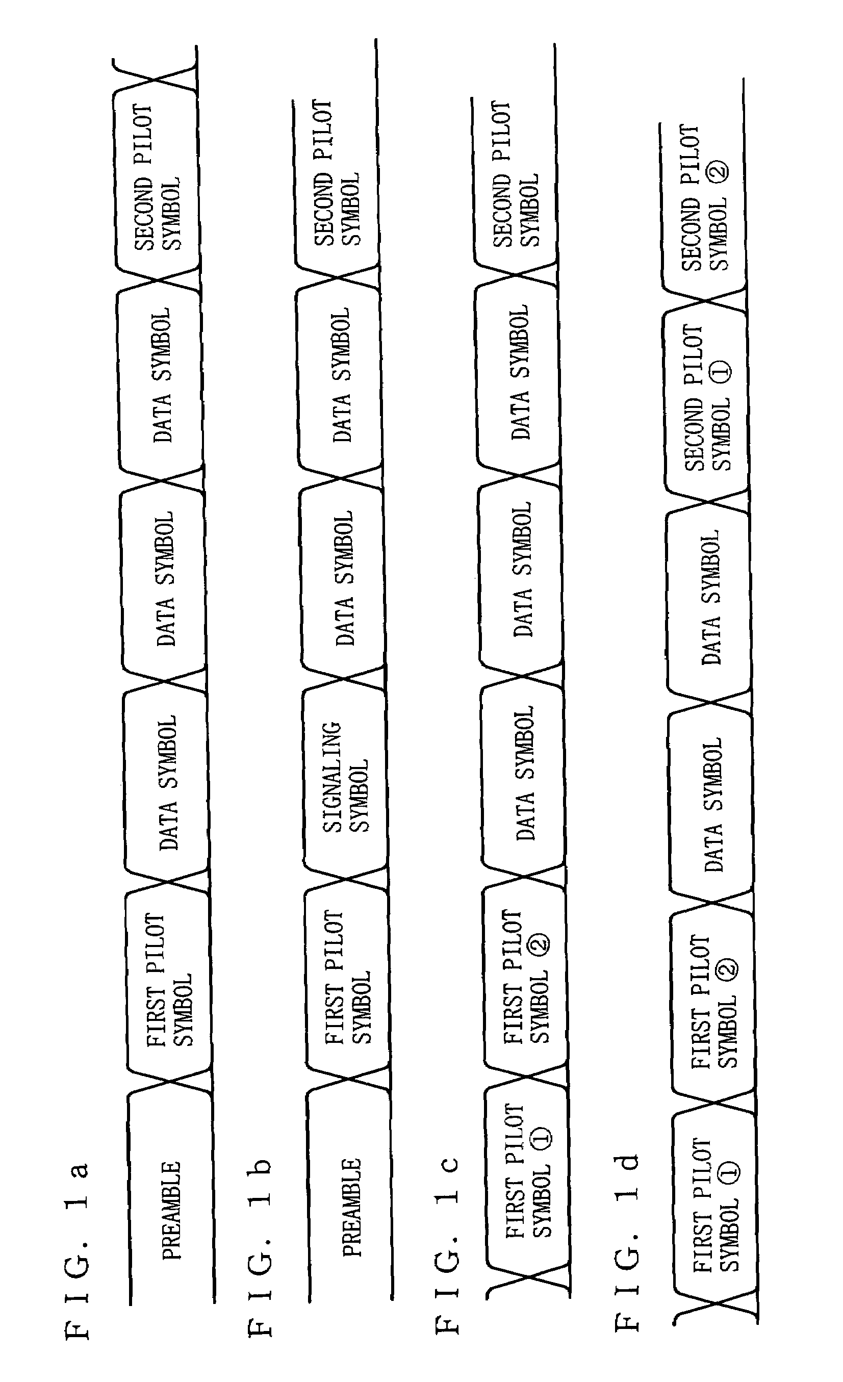
[0122]First, described below is a transmission scheme according to a first embodiment of the present invention. FIGS. 1a to 1d are diagrams each showing the structure of an OFDM signal to be transmitted under the transmission scheme of the first embodiment. As shown in FIG. 1, a pilot symbol is accompanied by a plurality of data symbols. The pilot symbol has a frequency component predetermined in amplitude and phase. After the data symbols, another pilot symbol follows. As such, the OFDM signal under the transmission scheme of the first embodiment takes such structure that the pilot symbol is inserted before and after one or more data symbols. Herein, the number of pilot symbols to be inserted is not limited, but in a row if plurally provided.

[0123]The OFDM signal includes subcarriers, and the symbol length remains the same regardless of the number of subcarriers included therein. Accordingly, the subcarriers may be predetermined in amplitude and phase wholly or partially. In order ...

second embodiment

[0167]A transmission scheme according to a second embodiment of the present invention is quite similar to the one described in the first embodiment. Further, a transmitter of the second embodiment is structurally identical to the one in the first embodiment, and is not described twice. As to a receiver of the second embodiment, however, is partially different in structure from the one in the first embodiment, and thus description is made focusing on the difference.

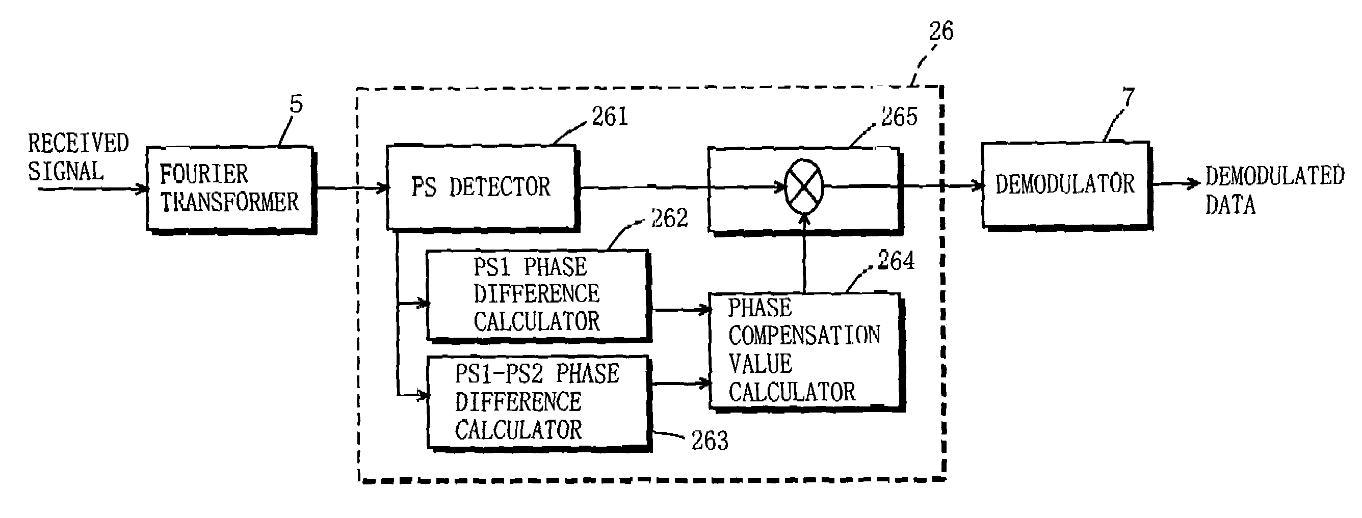
[0168]FIG. 10 is a schematic view showing the structure of the receiver of the second embodiment. The receiver is provided with the Fourier transformer 5, a phase compensator 26 for compensating a phase of a signal provided by the Fourier transformer 5, and the demodulator 7 for demodulating a signal outputted from the phase compensator 26. As such, the receiver of the second embodiment includes the phase compensator 26 as an alternative to the TPFR compensator 6 in the receiver in FIG. 4.

[0169]The phase compensator 26 fre...


PUM


Abstract

In an OFDM transmission scheme, in order to compensate any frequency response variations time wise resulted from any distortion in a transmission path, out-of-synchronization with passage of time, frequency drift, and phase shift, and to improve a demodulation characteristic, a PS detector in a receiver receiving an OFDM signal detects a pilot symbol. A PS1 TPFR calculator calculates a frequency response of the transmission path for a first pilot symbol, while a PS2 TPFR calculators calculates a frequency response of the transmission path for a second pilot symbol for a second pilot symbol. Thereafter, a compensation vector calculator calculates compensation vectors from the frequency responses of the transmission path for both of the first and second pilot symbols by linear approximation. A frequency response compensatory compensates the frequency response variation of subcarriers in a data symbol based on the calculated compensation vectors.

Description

BACKGROUND OF THE INVENTION[0001]1. Field of the Invention[0002]The present invention relates to an OFDM (Orthogonal Frequency Division Multiplexing) transmission scheme, and more specifically to a scheme for transmitting data via a wired or wireless transmission path by using an OFDM signal, and a transmitter / receiver therefor.[0003]2. Description of the Background Art[0004]In an OFDM signal transmission scheme, a demodulation characteristic deteriorates due to any distortion observed in a transmission path, out-of-synchronization after passage of time, frequency drift between a transmission side and a reception side, amplitude and phase errors resulted from phase noise in a local oscillator provided in a receiver, and the like. Such error factors provoking the demodulation characteristic to deteriorate are hereinafter referred to as frequency response variation.[0005]In the OFDM signal transmission scheme, for synchronization with a receiver, a transmitter often inserts one or mor...

Claims


Application Information

Patent Timeline
IPC IPC(8): H04J3/06
CPCH04L5/0048H04L5/0085H04L27/2675H04L25/0226H04L27/2613H04L27/2657H04L25/022H04L5/0007H04L5/006H04L25/0232H04L27/26134
Inventor NAKAHARA, HIDEKITANAKA, KOICHIROSHIRAKATA, NAGANORIKIMURA, TOMOHIROHARADA, YASUO
Owner INTERDIGITAL PATENT HLDG INC
Learn More