Fiber transition segment for use in optical fiber hydrophone array

a technology of transition segment and optical fiber, which is applied in the direction of instruments, optical elements, transducers for subaqueous use, etc., can solve the problems of deformation of optical fiber, mechanical fragility of optical fiber, and degraded light transmission, so as to achieve reliable and protected

Inactive Publication Date: 2006-04-11
GENERAL DYNAMICS ADVANCED INFORMATION SYSTEMS
View PDF62 Cites 77 Cited by
  • Summary
  • Abstract
  • Description
  • Claims
  • Application Information

AI Technical Summary

Benefits of technology

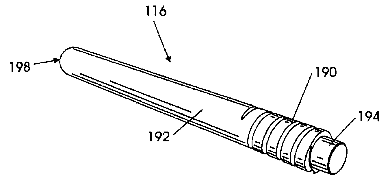
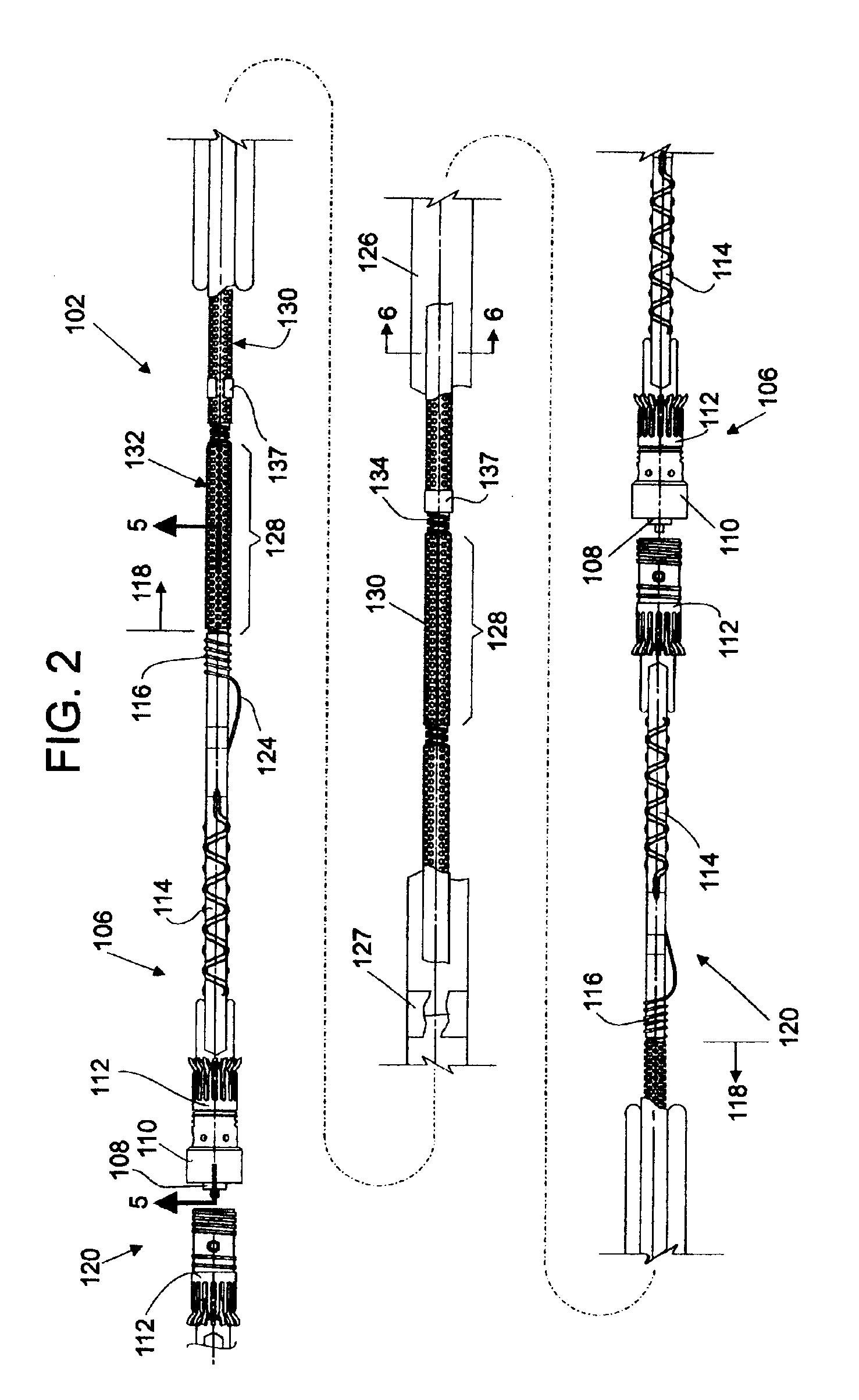
[0012]In still further accord with the present invention, the optical fiber is wrapped around the conical body within the helical groove in three stages. The optical fiber is wrapped from the end adjacent to the interconnect spring in the first stage for two to three revolutions around the conical body, and then in the second stage within a tube, continuing around the conical body within the helical groove for two to three revolutions. In the third stage the helical groove ends and the fiber in the tube is wrapped three to five more revolutions around the conical body before transitioning to the central axis of the module. The fiber in the first stage is bonded within the helical groove, the tube in the second stage is bonded within the helical groove, and the tube in the third stage is loosely wrapped around the conical exterior. The winding stages provide a reliable, protected transition of the optical fiber from the hydrophone assembly to the central axis of the module. In yet still further accord with the present invention, the tube is made of polytetrafluoroethylene. Also provided according to the present invention is an optical fiber hydrophone module having a fiber transition segment.

Problems solved by technology

While large bandwidth capabilities and small size make optical fibers desirable for use, optical fibers are mechanically fragile.
Tow-induced loads may cause the fibers to fracture.
Radial compressive loads may cause degraded light transmission as the result of a phenomenon known as microbending loss.
Stress corrosion is another cause of failure of optical fibers, and is a stress-accelerated chemical reaction between the optical fiber glass and water that can result in microcracks in the glass, adversely effecting fiber performance.
Optical fibers serving individual modules are limited in the number of light transmission channels available for communication with the monitoring equipment in the vessel.
Such connectors include fiber splice trays, which are commercially available, but are too large for retrofitting into thin-line towed sonar arrays.

Method used


Image

  • Fiber transition segment for use in optical fiber hydrophone array
  • Fiber transition segment for use in optical fiber hydrophone array
  • Fiber transition segment for use in optical fiber hydrophone array

Examples


Embodiment Construction

[0059]Certain terminology is used herein for convenience only and is not to be taken as a limitation on the invention. For example, words such as forward, aft, upper, lower, left, right, horizontal, vertical, upward, and downward merely describe the configuration shown in the Figures. The components may be oriented in any direction and the terminology, therefore, should be understood as encompassing such variations unless specified otherwise. Also, the scope of the invention is not intended to be limited by the materials or dimensions listed herein, but may be carried out using any materials and dimensions that allow the construction and operation of the hydrophone module.

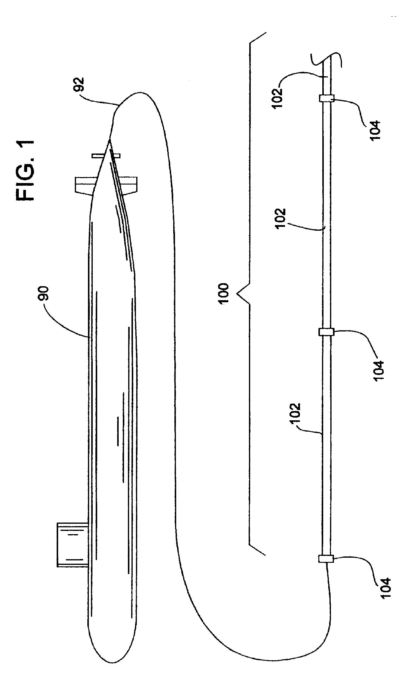
[0060]Referring now to the drawings, wherein like reference numerals illustrate corresponding or similar elements throughout the several views, there is shown in FIG. 1 a submarine 90 using a tow cable 92 to tow an optical hydrophone sonar array 100. The hydrophone array 100 is a linear array of modules 102 connect...


PUM


Abstract

A fiber transition segment for transitioning an optical fiber from a hydrophone module to the central axis of the module. The segment comprises a conical, elongated element and a cylindrical portion of reduced diameter that protrudes longitudinally from the wide end of the conical element. The cylindrical portion is reciprocally mounted within an interconnect spring at the end of the hydrophone assembly. The fiber transition segment has a helical internal groove for receiving the optical fiber from the interconnect spring. The groove is aligned with and approximately matches the pitch of the groove in the interconnect spring to provide a smooth transition to the fiber transition segment and then to the central axis of the module.

Description

FEDERAL RESEARCH STATEMENT[0001]This invention was made with Government support under Contract N00024-98-C-6308. The Government has certain rights in this invention.BACKGROUND OF INVENTION[0002]The science of underwater sonar equipment is increasingly relying on the use of fiber-optic technology. This reliance is driven by the requirement to have more acoustic sensors per sonar system, with higher sensitivities and lower cost.[0003]Passive sonar arrays towed from submarines or surface ships are excellent candidates for fiber-optic sensor technology. In this area, an all optical fiber hydrophone assembly is a recent development by the United States Naval Research Laboratories. The hydrophone assembly consists of a series of air-backed plastic cylinders, called mandrels, which are helically wrapped with optical sensing fiber. The hydrophone senses sound pressure levels through the strain induced in the optical sensing fiber as the sound pressure wave deforms the mandrel. Strain is imp...

Claims


Application Information

Patent Timeline
Patent Type & Authority Patents(United States)
IPC IPC(8): H04R1/44G02B6/44
CPCG02B6/4428
Inventor COOKE, DONALD A.MCGOVERN, KENNETH M.
Owner GENERAL DYNAMICS ADVANCED INFORMATION SYSTEMS
Why Eureka
Try Eureka