Electric heater for a semiconductor processing apparatus

a technology for processing apparatuses and electric heaters, applied in lighting and heating apparatus, muffle furnaces, furnaces, etc., can solve the problems of increased loading, deformation and/or breaking of metal resistance heating elements, and limited temperature setting of heat treating equipment employing this type of heating elements, so as to reduce the cost, the effect of high loading and high loading

a technology for processing apparatuses and electric heaters, applied in lighting and heating apparatus, muffle furnaces, furnaces, etc., can solve the problems of increased loading, deformation and/or breaking of metal resistance heating elements, and limited temperature setting of heat treating equipment employing this type of heating elements, so as to reduce the cost, the effect of high loading and high loading

US7027722B2Inactive Publication Date: 2006-04-11KOYO THERMO SYST CO LTD

Image

  • Electric heater for a semiconductor processing apparatus
  • Electric heater for a semiconductor processing apparatus
  • Electric heater for a semiconductor processing apparatus

Examples


Embodiment Construction

[0019]Best mode for carrying out the present invention is explained below, referring to the drawings.

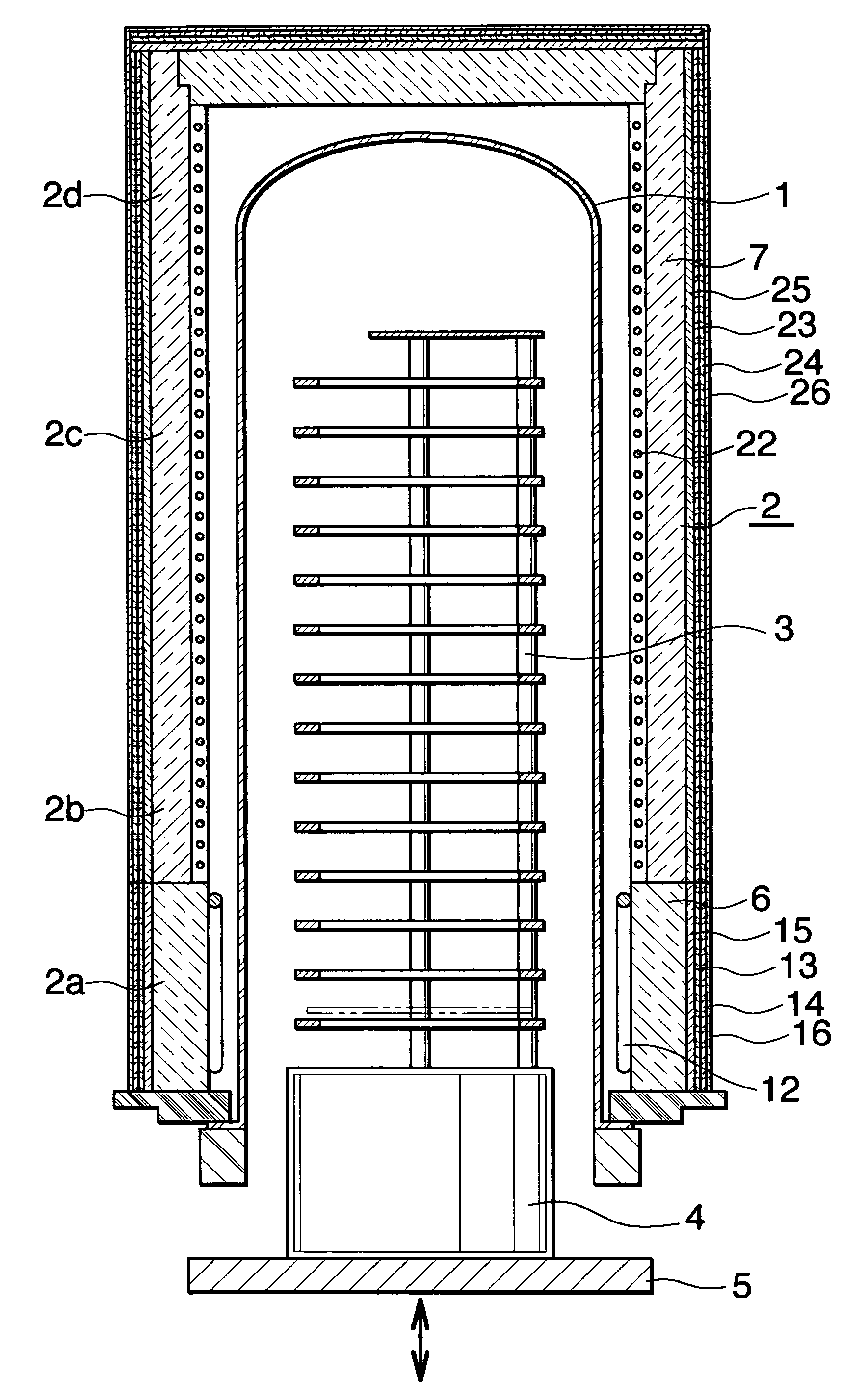
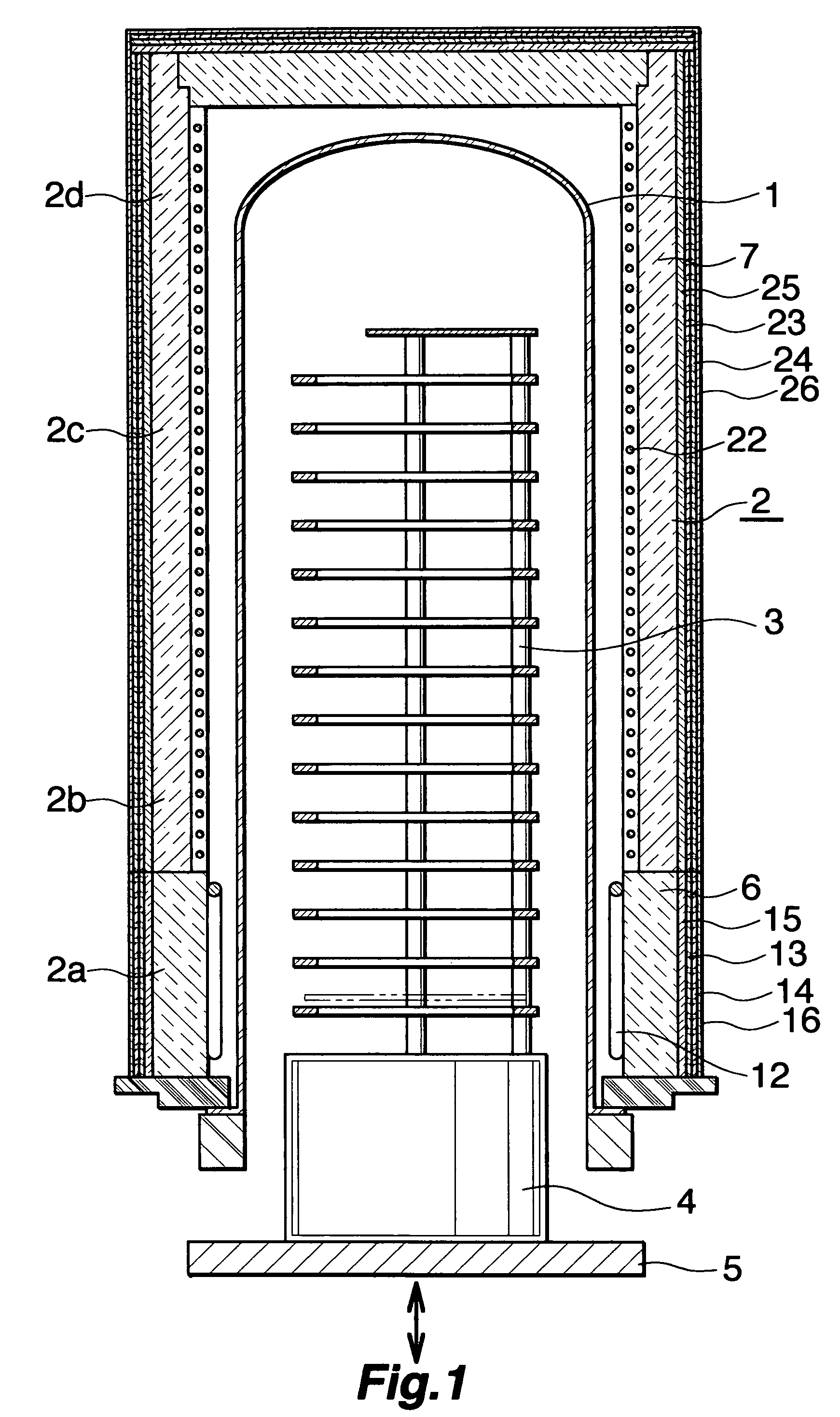
[0020]FIG. 1 shows a vertical diffusion furnace which is an example of a semiconductor processing equipment, in which an electric heater by the present invention is employed; the vertical diffusion furnace comprises a process tube (1) to perform a heat treatment for semiconductor wafers, an electric heater (2) installed surrounding the process tube (1), a boat (3) which is mounted on a heat insulating cylinder (4) and can carry a number of semiconductor wafers, and a flange cap (5) which supports the heat insulating cylinder (4), performs a vertical movement (up / down), and closes a boat insertion opening at the bottom end of the process tube (1) at the time of the treatment.

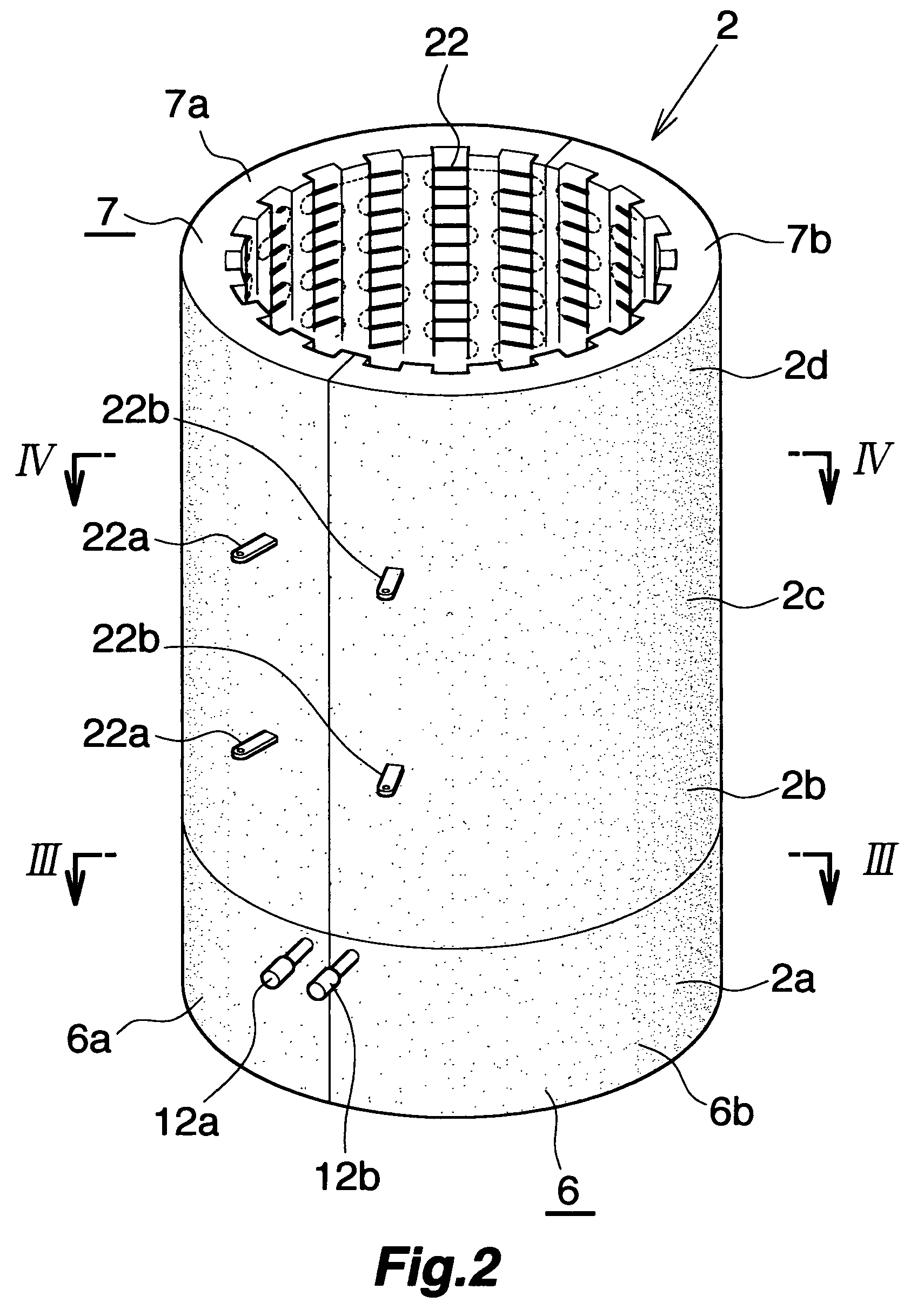
[0021]The electric heater (2) is sectioned in four control zones consisting of the bottom zone (2a) as the end zone, the middle zones (2b)(2c) consisting of two zones, and the top zone (2d); the electric heater (2...


PUM

PropertyMeasurementUnit
diameteraaaaaaaaaa
diameteraaaaaaaaaa
temperatureaaaaaaaaaa

Abstract

An electric heater has multiple zones, wherein the multiple zones include at least one zone which is subject to high loading (e.g. bottom zone) and, at least one zone is a non-metal heating element, and the rest of the zones (e.g. middle zone and top zone) are metal resistance heating elements of light gauge overbent.

Description

TECHNICAL FIELD[0001]The present invention relates to an electric heater which is preferably used for an apparatus to perform heat treatments such as oxidation, diffusion, and / or CVD on semiconductor wafers.BACKGROUND ART[0002]Conventionally, an electric heater for a batch type heat-treating equipment for semiconductor wafers is known, such as one employing a metal resistance heating element (cf. Japanese Patent Unexamined Publication No. 2001-267261 bulletin), and another employing a non-metal resistance heating element (cf. Japanese Patent Bulletin No. 3307924).[0003]A heating element as described in Japanese Patent Unexamined Publication No. 2001-267261 bulletin employs, as a metal wire, a Kanthal (brand name) wire made of iron / chrome / aluminum system or a similar material, of around 1–3 mm wire diameter called “light gauge”. Besides, a heating element which employs a Kanthal wire or a similar material, of around 7–10 mm wire diameter called “heavy gauge” is used. In case of a hea...

Claims


Application Information

Patent Timeline
11 Apr 2006
Publication
US7027722B2
IPC
F26B19/00; H01L21/00; H01L21/205; H01L21/22
CPC
H01L21/67109
Inventors
UEMORI, SUSUMU; AITANI, TAKASHI