Retracting apparatus, drawer apparatus and sliding door apparatus

a technology for sliding doors and drawers, applied in the field of retracting devices, can solve the problems of complex structure of the apparatus, increased cost, complex adjustment, etc., and achieve the effect of simple structure and inexpensive cos

Active Publication Date: 2006-04-18
THK CO LTD
View PDF13 Cites 53 Cited by
  • Summary
  • Abstract
  • Description
  • Claims
  • Application Information

AI Technical Summary

Benefits of technology

[0007]Taking the matter mentioned above into consideration, an object of the present invention is to provide a retracting apparatus, a drawer apparatus and a sliding door apparatus in which a self locking state is not cancelled without intention, a structure and an adjustment are simple, and a cost is inexpensive.

Problems solved by technology

As a result, there is a problem that a structure of the apparatus is complex and a cost increase is generated.
Accordingly, there is a problem that an adjustment is complex.

Method used


Image

  • Retracting apparatus, drawer apparatus and sliding door apparatus
  • Retracting apparatus, drawer apparatus and sliding door apparatus
  • Retracting apparatus, drawer apparatus and sliding door apparatus

Examples


Embodiment Construction

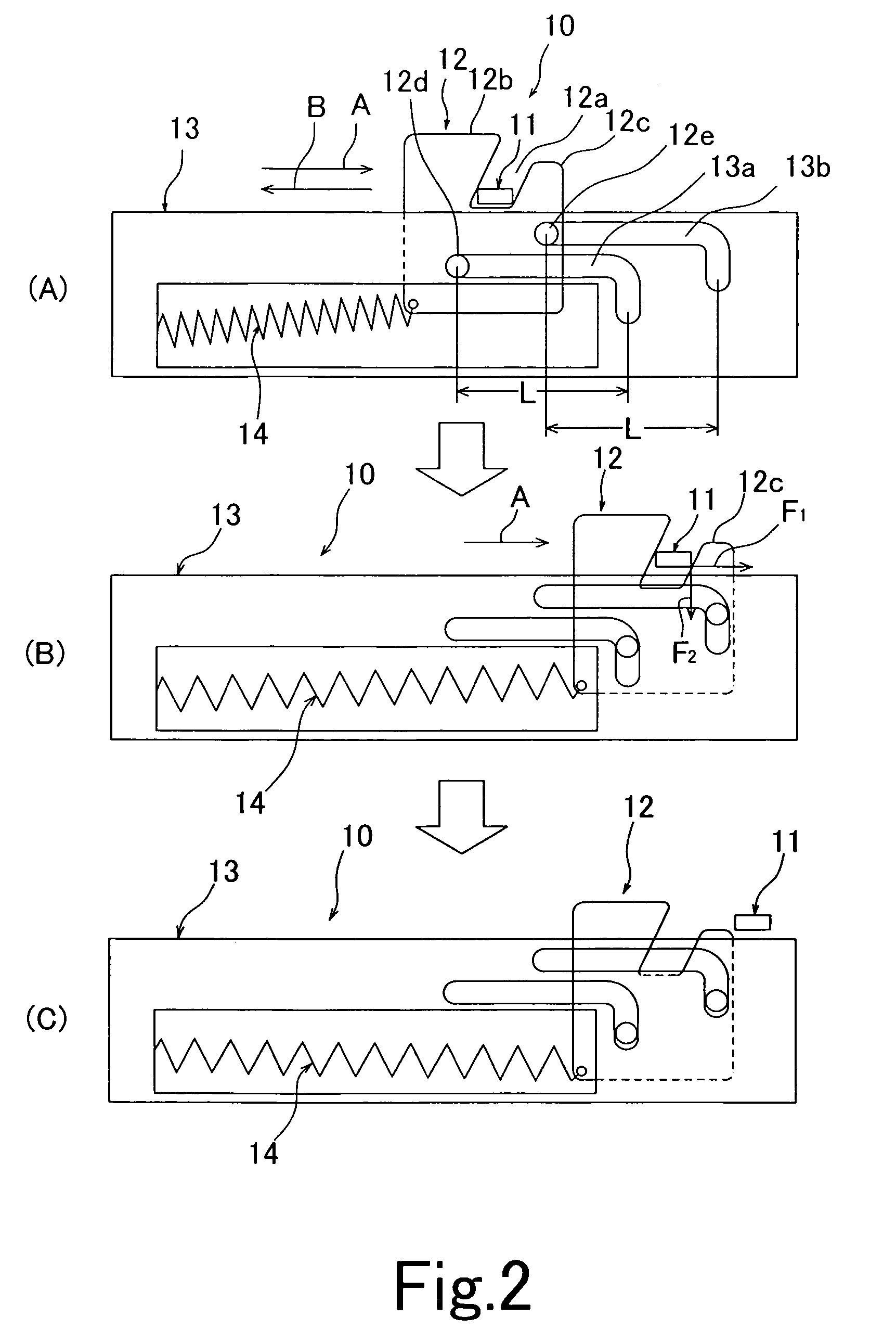
[0073]A description will be given below of an embodiment in accordance with the present invention with reference to the accompanying drawings. FIGS. 2 and 3 are views showing a structure and an operation of a retracting apparatus in accordance with the present invention.

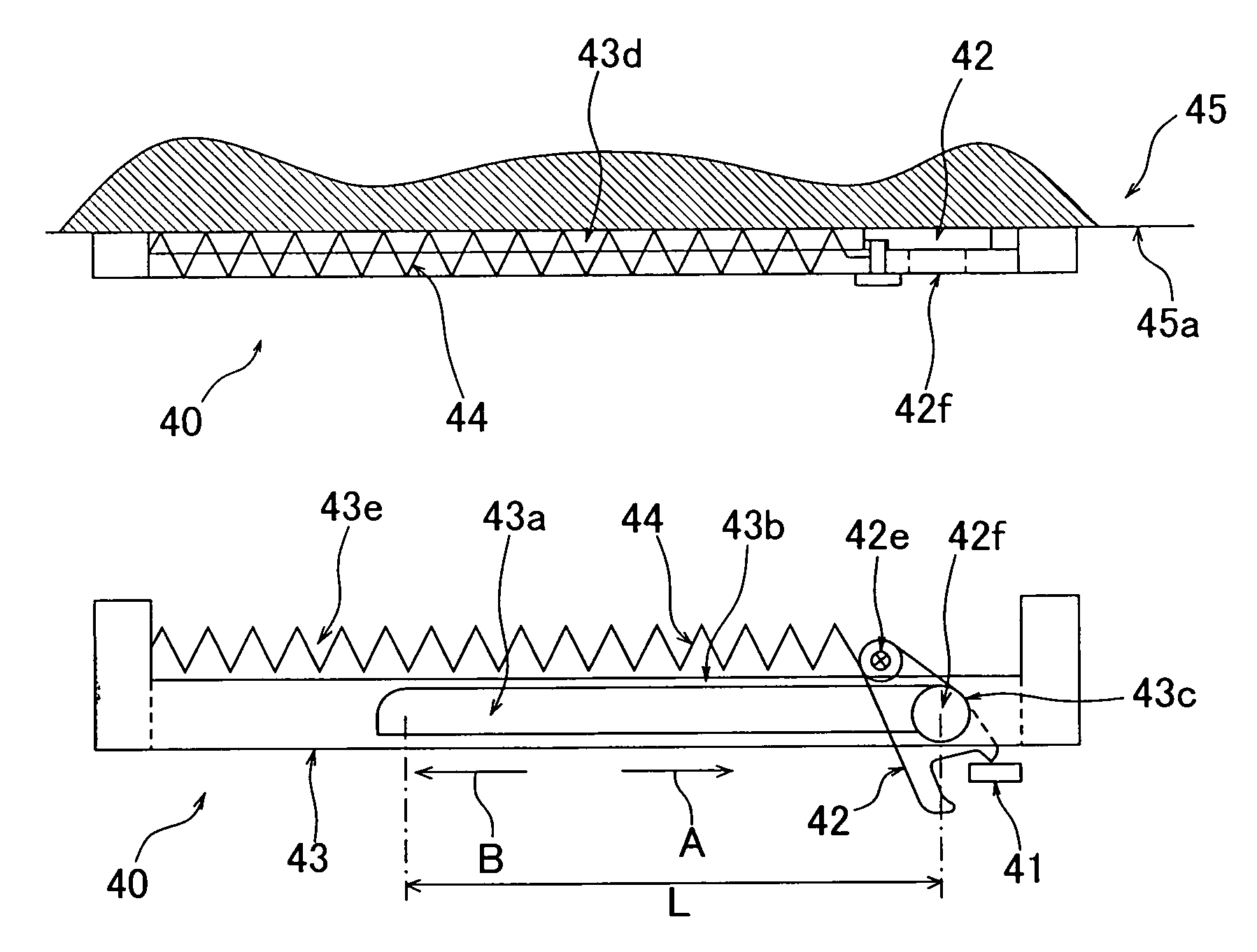
[0074]A retracting apparatus 10 is provided with a driving member 11 moving interlocking with a moving rail (described in detail later) (not shown), an engagement member 12 engaging with the driving member 11, a guiding member 13 guiding the engagement member 12, and a coil spring 14 corresponding to an energizing member energizing the engagement member 12 in a retracting direction (an arrow B).

[0075]The engagement member 12 is constituted by a plate-shaped body, and is structured such that an engagement groove portion 12a engaged with the driving member 11 is formed in an upper portion thereof, a projection portion 12b having a predetermined height is provided in a retracting side (an arrow B side) with respect to t...


PUM


Abstract

The invention provides a retracting apparatus of a sliding rail in which a self locking state is not cancelled without intention, a structure and an adjustment are simple, and a cost is inexpensive. In the retracting apparatus of the sliding rail, a guiding member (13) is provided with two parallel arranged guiding grooves (13a, 13b) which are linear in a predetermined range of a drawing and retracting direction, and are bent at a predetermined amount toward an approximately vertical lower side in an end portion in a drawing direction, an engagement member is provided with sliding pins (12d, 12e), and the sliding pins (12d, 12e) slide along the guiding grooves (13a, 13b) in accordance with movement in the drawing direction, and moves downward at a predetermined amount in an end portion in the drawing direction, whereby an engagement between the engagement member (12) and a driving member (11) is cancelled, the engagement member (12) is locked, the driving member (11) and the engagement member (12) are engaged with each other at an automatic retract position on the basis of the movement of the moving rail in the retracting direction, and the lock is cancelled.

Description

BACKGROUND OF THE INVENTION[0001]The present invention relates to a retracting apparatus which is provided with a fixed body and a moving body supported to the fixed body so as to freely move in a predetermined range, and when the moving body moves from one moving end position or another moving end position in a direction of the another moving end position or in a direction of the one moving end position, and reaches an automatic retract position a predetermined distance apart from the another moving end position or the one moving end position, is automatically retracted to the another moving end position or the one moving end position, such as a drawer apparatus, a sliding door apparatus or the like.[0002]Conventionally, as this kind of retracting apparatus, there is a closing apparatus for a drawer which is disclosed in Japanese Unexamined Patent Publication No. 5-23763.[0003]The closing apparatus for the drawer is a closing apparatus for a drawer which is constituted by supportin...

Claims


Application Information

Patent Timeline
Patent Type & Authority Patents(United States)
IPC IPC(8): E05D15/00A47B88/04E05F1/08
CPCA47B88/047E05F1/16E05F5/003Y10T16/379E05Y2201/412Y10T16/593Y10T16/361E05Y2900/20A47B88/467E05Y2800/24
Inventor HOSHIDE, KAORUSASAKI, SOICHI
Owner THK CO LTD
Why Eureka
Try Eureka