Wire mesh chair

a wire mesh and chair technology, applied in the field of chairs and spacers, can solve the problems of not always being able to stack prior art chairs, not being able to effectively support wire mesh, and corrosion, and achieve the effects of convenient use of wire mesh, convenient packaging, and convenient manufacturing

Inactive Publication Date: 2006-04-18
DAYTON SUPERIOR CORP
View PDF13 Cites 14 Cited by
  • Summary
  • Abstract
  • Description
  • Claims
  • Application Information

AI Technical Summary

Benefits of technology

[0007]One objective of the present invention is to provide a chair designed specifically to fixedly retain wire mesh. Another objective of the invention is to provide a wire mesh chair that can be stacked within another chair to provide a more efficient method for packaging, storage, shipment and ease of handling and convenience at the job site. It is a further objective of the present invention to provide a wire mesh chair with a wide base that allows the chair to stand securely. It is also an objective to provide a plastic chair made of durable, non-corrosive materials that is easy to manufacture and easy to use with wire mesh.

Problems solved by technology

Once the steel is exposed to the effects of chemical-laden moisture, corrosion starts taking effect.
While the prior art chairs described above may be useful for their respective, particular objectives, the majority are generally intended for support of rebar or post-tensioning cables, which is not always effective for the support of wire mesh.
Also, most prior art chairs are not able to be stacked, and therefore require an inordinate amount of space for shipping and storage.
Other chairs lack retention means to reliably secure the reinforcement members.

Method used


Image

  • Wire mesh chair
  • Wire mesh chair
  • Wire mesh chair

Examples


Embodiment Construction

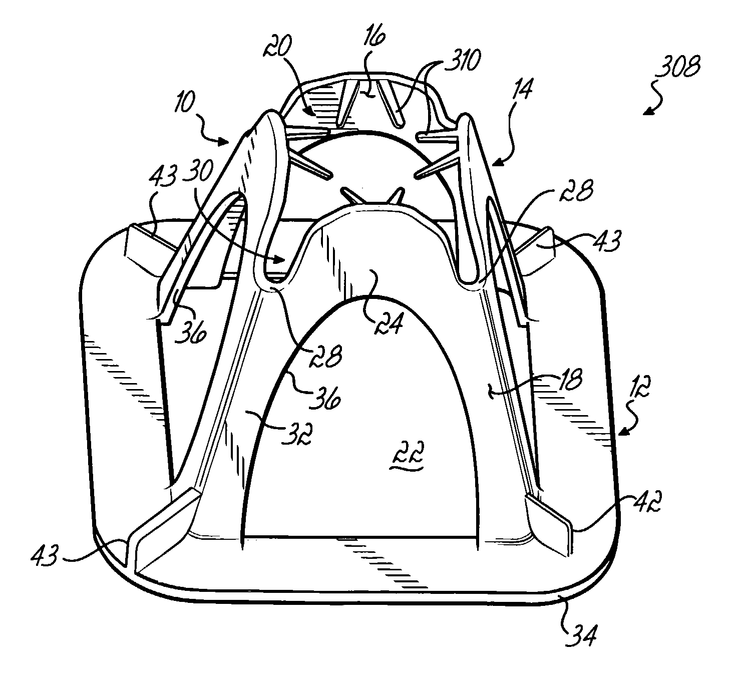
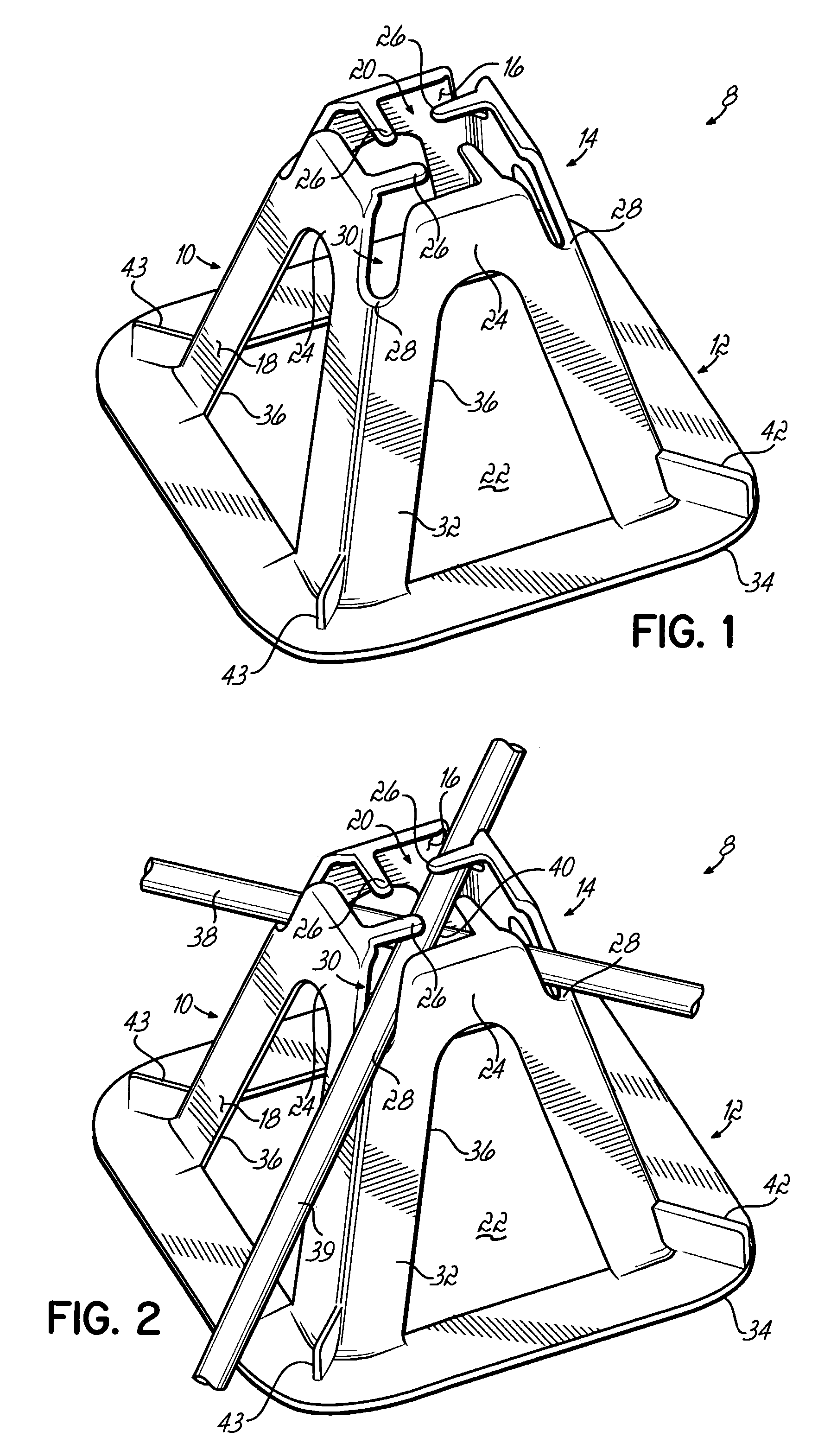
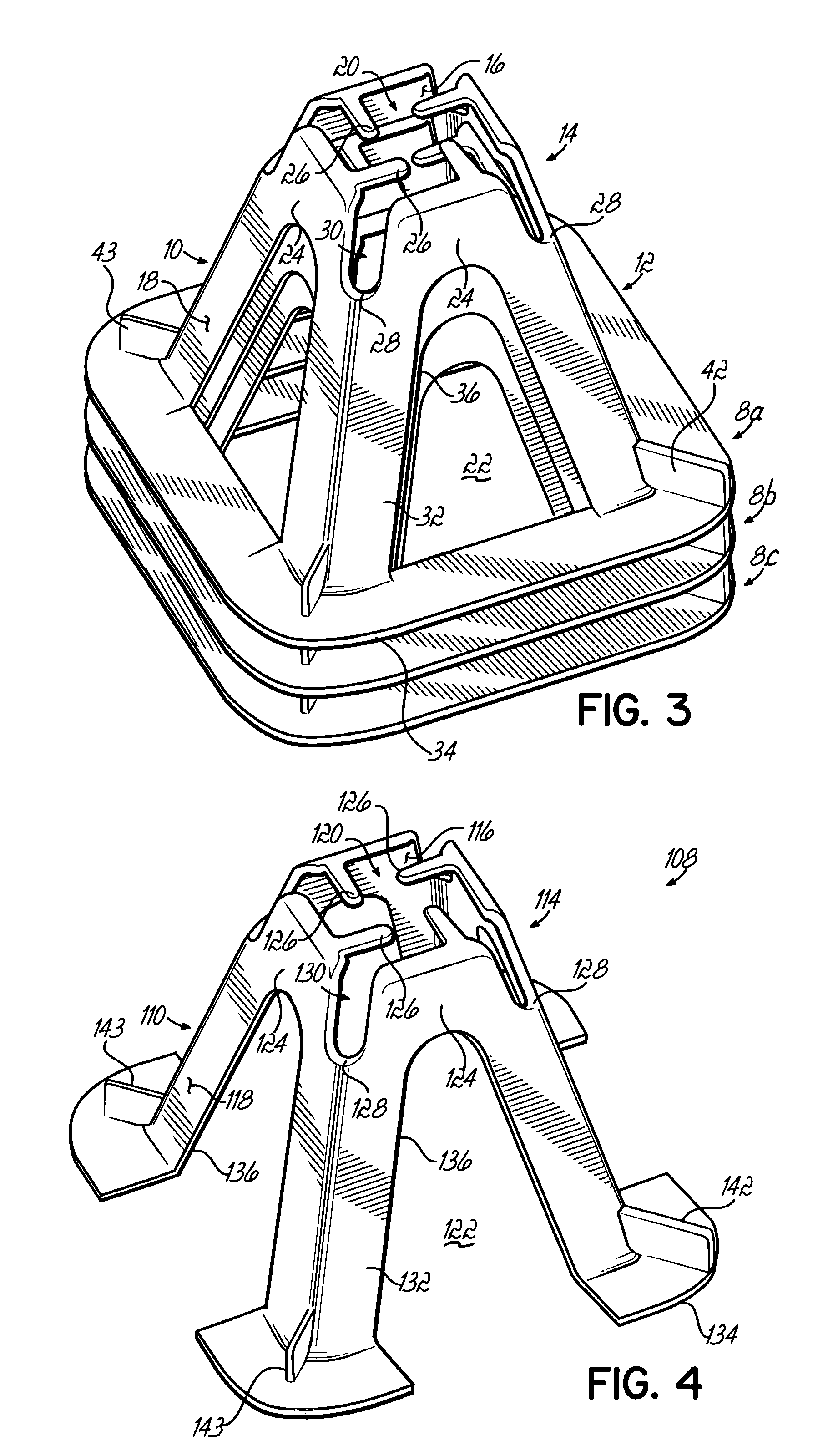
[0023]Referring now to FIG. 1, a perspective view is shown of one embodiment of the wire mesh chair 8 of the present invention having a hollow body 10 including a base 12, a receiving area 14, an inner surface 16, and an outer surface 18. There is an upper opening 20 defined by the receiving area 14 and a lower opening 22 defined by the base 12. Receiving area 14 has a plurality of walls 24 with inwardly facing detents 26. Walls 24 project upwardly between generally rounded notches 28. Between the notches 28 are passageways 30 defined by the walls 24. The lower base 12 has a plurality of separate support legs 32 extending downwardly from the receiving area 14. A foot member 34 extends horizontally outwardly from legs 32. Adjacent support legs 32 define holes or apertures 36, which allow poured concrete to fluidly pass through the wire mesh chair 8. At the base of the support legs are projections, one long projection 42 and three short projections 43.

[0024]The chair of FIG. 1 is pref...


PUM

PropertyMeasurementUnit
widthaaaaaaaaaa
degree angleaaaaaaaaaa
areaaaaaaaaaaa

Abstract

A chair for supporting wire mesh while pouring concrete slabs. The chair has a generally tapered, hollow body with a receiving area for fixedly retaining the wire mesh. The receiving area includes walls extending upwardly between notches, with the walls defining passageways for guiding the mesh into the notches. Detents project inwardly from the tops of the walls to fixedly retain the mesh within the passageways. The body has inner and outer surfaces that are substantially complementary to one another to allow a plurality of chairs to be stacked together. One or more foot members are preferably attached to the lower base portion to provide for secure support of the chair on a variety of surfaces.

Description

FIELD OF THE INVENTION[0001]The present invention relates generally to chairs and spacers that are used in construction activities for the support of steel reinforcement members, and in particular to stackable chairs that are reliably able to retain welded wire mesh within concrete slabs.BACKGROUND OF THE INVENTION[0002]Chairs or spacers are commonly used in the construction industry for the support and positioning of steel reinforcement members, such as wire mesh, post-tension cables and / or reinforcement bars (“rebar”), a proper distance above a surface. The bars or cables are usually arranged in rows or grids within an area into which concrete is to be poured. They are held loosely in place while concrete is placed around them. In normal[0003]Proper spacing and arrangement of steel reinforcement members in concrete slabs and / or tilt-up panels according to known engineering and architectural specifications impacts the structural strength and integrity of the concrete structure. Suc...

Claims


Application Information

Patent Timeline
Patent Type & Authority Patents(United States)
IPC IPC(8): E04C5/16E04C5/20
CPCE04C5/166E04C5/20E04C5/168
Inventor BENNETT, CLIFFORD D.LEE, KENNETH
Owner DAYTON SUPERIOR CORP
Why Eureka
Try Eureka