Submersible vehicle launch and recovery system

a technology for submersible vehicles and recovery systems, which is applied in the direction of vessel salvaging, floating buildings, vessel transportation, etc., can solve the problems of unsuitable launch and recovery systems for some types of submersible vehicles and the risk of damage to this equipment, and achieves the effect of simple us

Inactive Publication Date: 2006-04-18
ECA ROBOTICS
View PDF11 Cites 12 Cited by
  • Summary
  • Abstract
  • Description
  • Claims
  • Application Information

AI Technical Summary

Benefits of technology

[0006]It is desirable to provide a submersible vehicle launch and recovery system suitable for handling submersible vehicles that have fragile external equipment, and that is simple to use.
[0008]The system in the form of a grab may be used to easily pick up a handling feature projecting from a submersible vehicle without the risk of bumping into equipment on the outside of the vehicle. Once the submersible vehicle-handling element is correctly positioned relative to the jaws, the simple act of raising the arms will cause the said jaws to close on the handling feature, so that the submersible vehicle may easily be gripped by the launch and recovery system. Moreover, provided the buoyancy means are appropriately distributed, the jaws of the arms will open spontaneously during submersible vehicle launch when the vehicle is lowered into the water, at the point when the buoyancy means are partly or completely submerged.
[0010]In one embodiment a buoyancy means is provided in the form of a hollow float equipped with fluid filling and evacuation means, the fluid being air and / or water in particular. This makes it easy to control the buoyancy of the buoyancy means in order to open the arms of the launch and recovery system at the desired depth.

Problems solved by technology

However, such launch and recovery systems are unsuitable for some types of submersible vehicle, particularly submersible vehicles with fragile external equipment on an outer surface of the vehicle, such as propulsion units or measuring instruments.
In this case there is a risk of damage to this equipment.

Method used


Image

  • Submersible vehicle launch and recovery system
  • Submersible vehicle launch and recovery system
  • Submersible vehicle launch and recovery system

Examples


Embodiment Construction

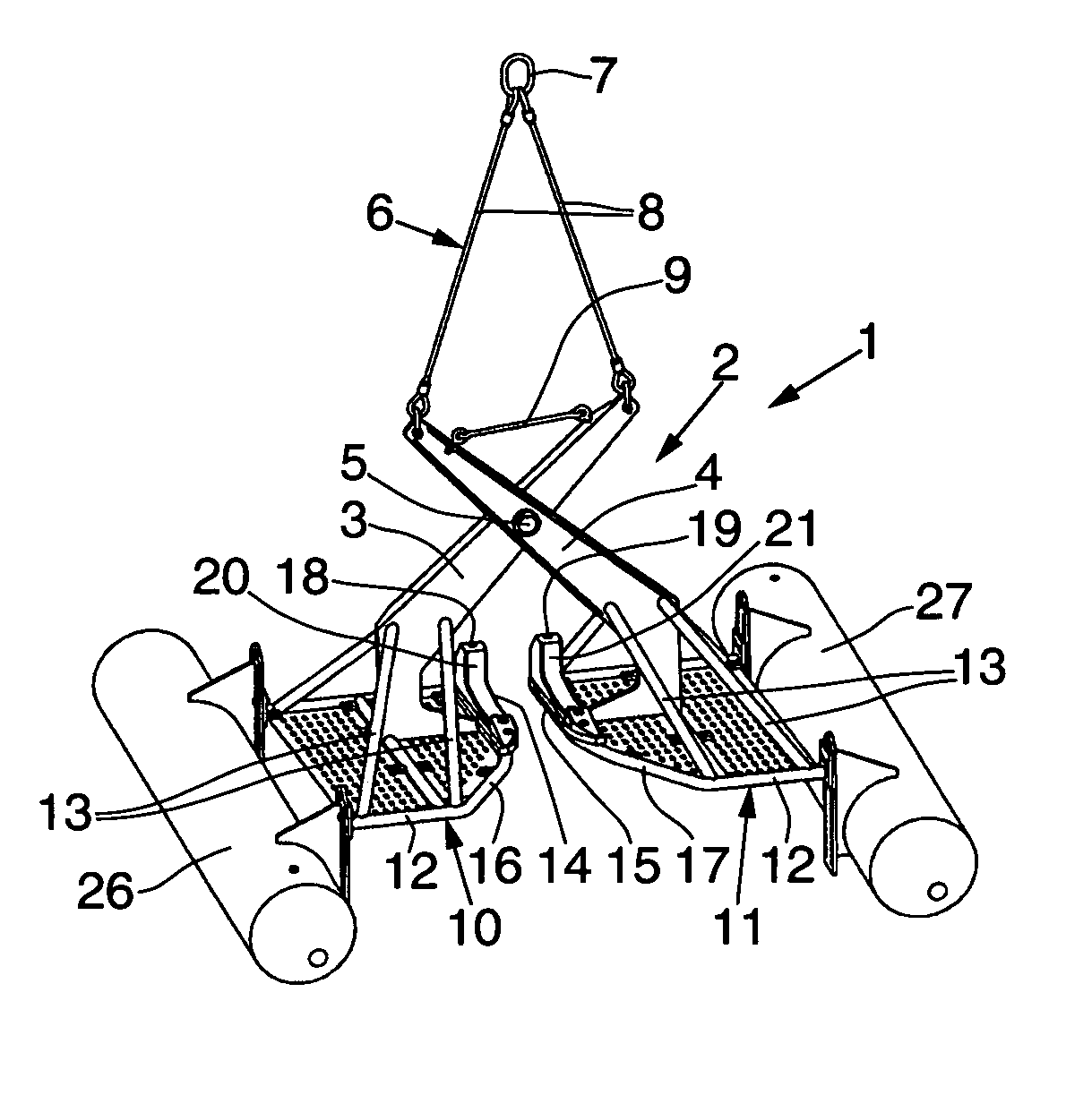
[0023]In FIG. 1 the launch and recovery system 1 includes a grab 2 formed by two arms 3, 4 arranged in a cross and coupled together by a hinge pin 5 at the intersection between the arms 3, 4. Top ends of the arms 3, 4 have means of attachment, here in the form of rings passed through holes in the ends of the arms 3, 4. A lifting sling 6 comprises a main ring 7 and two lines 8, each line being coupled at one end to the main ring 7 and at the other to the arm 3, 4 attachment means.

[0024]The system 1 includes an opening limiter that takes the form of a link 9 whose ends are attached to the top ends of the arms 3, 4 in such a way that the link 9 inhibits separation of the top ends of the arms 3, 4 and thus limits the opening of the arms 3, 4. The link 9 may for example be a metal rod, a sling, a chain or a cord.

[0025]The lower ends of the arms 3, 4 have a C-shaped profile so that each bends towards the other arm at the bottom. Frames 10, 11 are attached to the lower ends of the arms 3, ...


PUM


Abstract

A submersible vehicle launch and recovery system comprises a grab comprising at least two arms capable of moving relative to each other, the arms being rotatable between an open position and a closed position, in which closed position the jaws of the arms are able to grip a handling feature on a submersible vehicle. The arms comprise attachment means so arranged that the arms tend to close when the system is suspended by the said attachment means, at least one arm comprising buoyancy means so distributed as to tend to open the said arm when the system is submerged.

Description

BACKGROUND OF THE INVENTION[0001]1. Field of the Invention[0002]The present invention relates to the handling of underwater machines, and in particular to a submersible vehicle launch and recovery system.[0003]2. Description of the Relevant Art[0004]Systems for launching and recovering submersible vehicles come in the form of a cage that can be open or closed to release or recover the submersible vehicle. Document FR 2 823 485 discloses a system having an upper frame and lower frame forming a cage, the frames being moveable vertically relative to each other to either secure the submersible vehicle or release it.[0005]However, such launch and recovery systems are unsuitable for some types of submersible vehicle, particularly submersible vehicles with fragile external equipment on an outer surface of the vehicle, such as propulsion units or measuring instruments. In this case there is a risk of damage to this equipment.SUMMARY OF THE INVENTION[0006]It is desirable to provide a submers...

Claims


Application Information

Patent Timeline
Patent Type & Authority Patents(United States)
IPC IPC(8): B63C7/00B63B23/58B63B27/16
CPCB63B27/36B63B23/58
Inventor BOUCHAUD, DAVID LAURENT CLAUDELE BIGOT, PIERRE-YVES EUGENE JEAN
Owner ECA ROBOTICS
Why Eureka
Try Eureka