Office chair

a technology for office chairs and chairs, applied in the field of office chairs, can solve the problems of complex structure of many conventional chairs, significant problems, and the operation of many control mechanisms that require substantial physical effort, and achieve the effects of convenient location and operation, high degree of adjustability, and convenient operation

Inactive Publication Date: 2006-04-18
JSJ SEATING COMPANY TEXAS
View PDF12 Cites 29 Cited by
  • Summary
  • Abstract
  • Description
  • Claims
  • Application Information

AI Technical Summary

Benefits of technology

[0012]In another preferred embodiment, the height push button operates a wing that actuates a toggle switch protruding from the top of the upper tube of the support column. The height push button is preferably mounted within the tension control knob, where it is readily accessible. As a result, the height control is easily located and operated.
[0013]In another preferred embodiment, recline limit control mechanism includes a lever that is preferably mounted to the shaft of the tension control knob where it is readily accessible. The lever is operatively connected to a rotor that extends and retracts a cable in response to rotation of the lever. The cable is connected to a stop that travels in the path of a trackway on the seat frame to limit movement of the seat frame and consequently the back. The recline limit control mechanism is simple and effective, yet provides a high degree of adjustability to the recline limit. The recline limit lever is mounted adjacent the tension knob and height control so that the various seat controls are arranged in a single location, where they are easily located and operated by the occupant.
[0014]In a second aspect, the present invention provides a lumbar support that includes a lumbar pad and a lumbar cam. In a preferred embodiment, the lumbar cam includes lobes of differing dimensions arranged along a shaft. The shaft is rotatably mounted to the lumbar pad, thereby permit adjustment of the contour of the lumbar region by rotation of the lumbar cam. In a more preferred embodiment, the lumbar pad and lumbar cam are exposed and visible to the occupant. In an even more preferred embodiment, the lumbar support is height adjustable. More specifically, the lumbar pad and lumbar cam are movably mounted within a vertical channel. The lumbar support provides a high level of vertical and depth adjustment to the lumbar region through simple rotation of the lumbar cam. The degree of adjustability can easily be adjusted by variations in the lobes of the lumbar cam. Further, the exposed lumbar support is aesthetically pleasing and permits visual inspection of its components.
[0015]In a third aspect, the present invention provides an armrest control mechanism that permits adjustment of the height and angle of the armpads. In a preferred embodiment, the armrest control mechanism for each armrest includes a tube movably mounted in an upright and a ratchet mechanism that permits the height of the tube in the upright to be raised simply by lifting the armpads. The ratchet mechanism preferably includes a reset mechanism that permits each tube to be lowered only after it has been raised to its upper extreme. The armrest height control mechanism provides a high degree of vertical adjustment and, because there are no actuators, is easily operated simply by lifting or lowering the armpads.
[0016]The armrest control mechanism also preferably includes an armpad pivot mechanism that permits pivotal adjustment of the armpads. The pivot mechanism generally includes a lower plug that carries the plunger of the ratchet mechanism and an upper plug that is affixed to the tube and rotatably mounted to the lower plug. The pivot mechanism permits the tube, and hence the armpad, to be rotated without rotating the plunger. This mechanism provides a high degree of adjustability and is easily incorporated with the armrest height control mechanism.
[0017]In a fourth aspect, the present invention provides a modular back assembly that permits variation in the overall shape of the back through the installation of interchangeable upper back portion components. In a preferred embodiment, the back defines a mounting platform that is adapted to receive any of a variety of upper back portions through a snap-fit connection. The mounting platform is preferably disposed at the upper extreme of the back such that the overall shape and height of the back is readily varied by differently shaped upper back portion components. The modular upper back portion permits inexpensive variation in the overall shape of the back, thereby eliminating the need for the design, development and manufacture of entirely different backs to meet different price points.

Problems solved by technology

The level of complexity of many conventional controls is such that locating and operating the appropriate actuator for a given adjustment feature can present significant problems.
Further, many control mechanisms require substantial physical effort to operate.
This effort can be particularly difficult for the aged and those suffering from arthritis, carpal tunnel syndrome or other similar problems.

Method used


Image

  • Office chair
  • Office chair
  • Office chair

Examples


Embodiment Construction

I. General Description

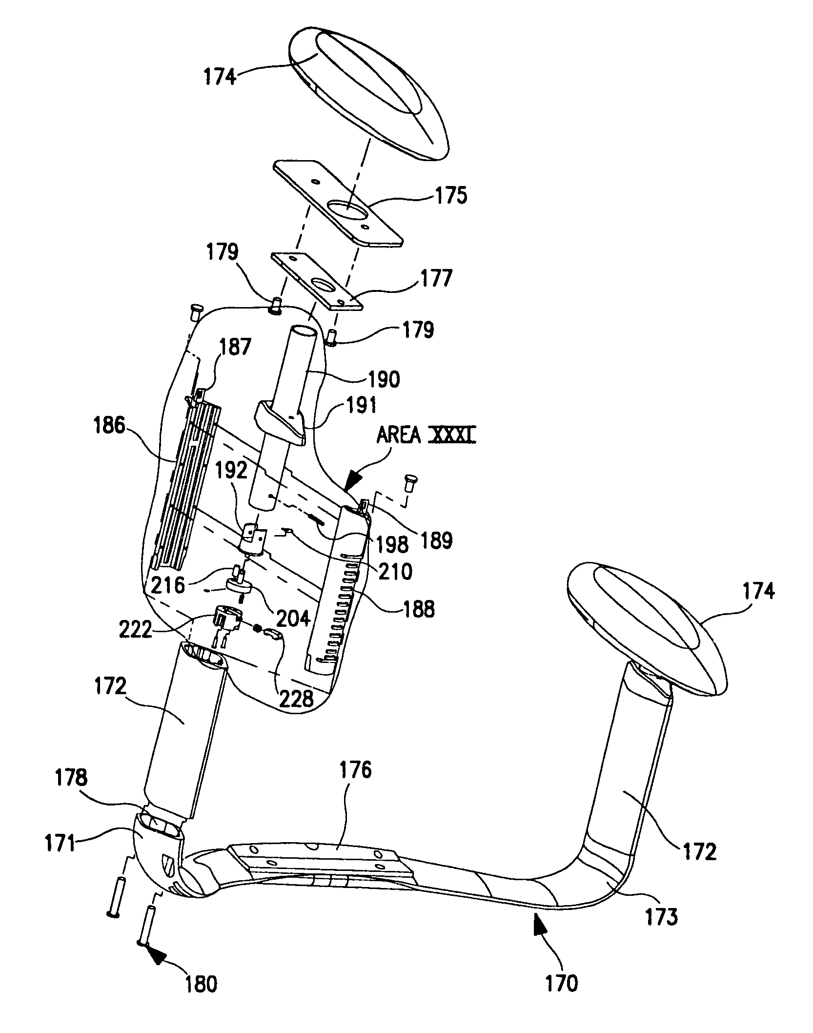
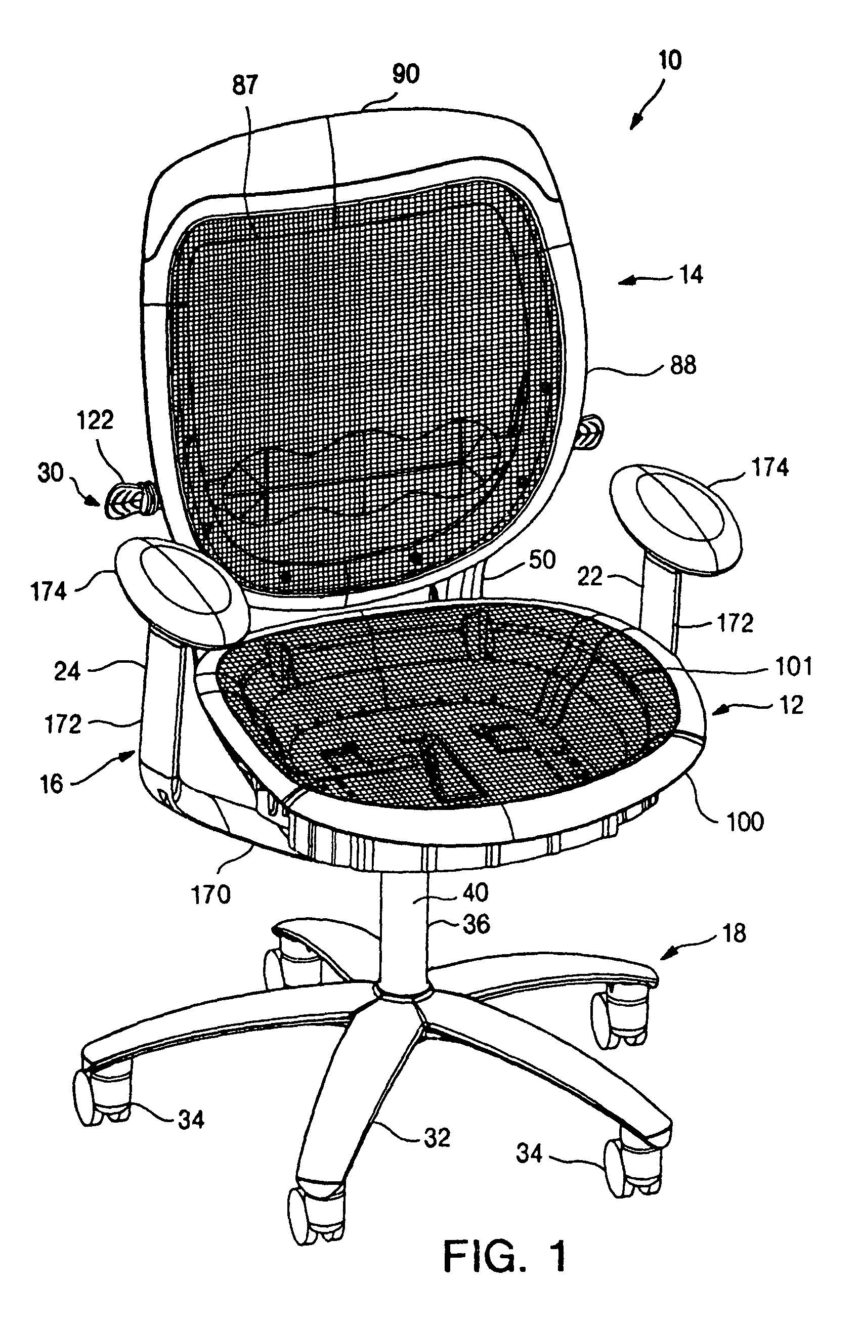
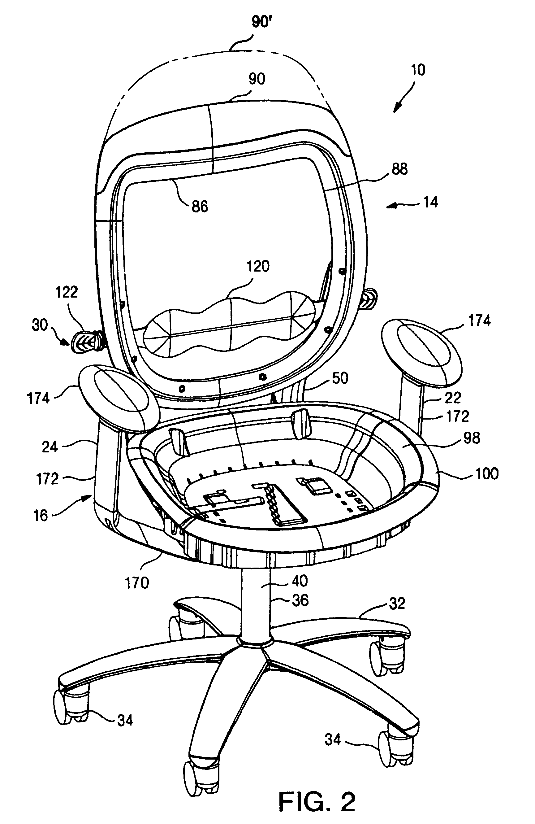
[0077]A chair in accordance with a preferred embodiment of the present invention is shown in FIGS. 1–2 and 51–55, and generally designated 10. In a preferred embodiment, the load bearing surfaces of the chair 10 are defined by load bearing fabric rather than conventional cushion and fabric constructions. The chair 10 is, however, illustrated with the load bearing fabric removed in all but FIG. 1 to show the structure of the present invention. The loading bearing fabric attachment of the preferred embodiment is described in detail in U.S. patent application Ser. No. 09 / 769,967, entitled LOAD BEARING FABRIC ATTACHMENT AND ASSOCIATED METHOD, which was filed on Jan. 25, 2001, by Timothy P. Coffield et al, which is incorporated herein by reference. Although the present invention is described in connection with a chair incorporating load bearing fabric, the present invention is well suit for use in other constructions, for example, conventional cushion and fabric con...


PUM


Abstract

A chair having an adjustable resilient back recliner mechanism, a pair of adjustable armrests, modular upper back portions and an adjustable lumbar support. The chair includes a tension control that adjusts the tension in the recliner mechanism. The tension control is cam-operated to permit adjustment throughout the entire range of adjustability with only limited rotational movement of a control knob. The chair includes a recline limit control that adjusts the limit of rearward movement in the recliner mechanism. The limit control includes a cable operated stop that interact with a stepped trackway on the seat. The chair further includes a height control for adjusting the seat height including a push-button located in the tension control knob. The armrests include height and angle adjustment mechanisms. The lumbar support includes a lumbar cam that is rotatably mounted to a lumbar pad. The lumbar cam includes a plurality of lobes that vary in radius so that rotation of the cam causes variation in the contour of the lumbar region. The chair back includes a fabric carrier with an upper back portion mounting platform that permits attachment of any of a variety of modular upper back portions.

Description

BACKGROUND OF THE INVENTION[0001]This application is a division of U.S. application Ser. No. 09 / 883,646, filed Jun. 18, 2001 (now U.S. Pat. No. 6,688,690), by Ronnie K. Watson et al, entitled OFFICE CHAIR, which is a continuation-in-part of U.S. patent application Ser. No. 09 / 769,967, filed Jan. 25, 2001, now U.S. Pat. No. 6,842,959 by Timothy P. Coffield et al, entitled LOAD BEARING FABRIC ATTACHMENT AND ASSOCIATED METHOD.[0002]The present invention relates to seating, and more particularly to office and task seating.[0003]To enhance comfort and provide improved ergonomic function, office and task seating is typically provided with a high degree of adjustability. For example, it is common to provide mechanisms for adjusting the height of the seat, the location of the armrest and the degree of lumbar support.[0004]Another common feature provided in some office and task seating is a resilient back recline. The resilient back recline permits the back to tilt or recline rearwardly in a...

Claims


Application Information

Patent Timeline
Patent Type & Authority Patents(United States)
IPC IPC(8): A47C7/54A47C7/44A47C1/02A47C1/03A47C1/032A47C3/026A47C7/46
CPCA47C1/03A47C1/03255A47C7/282A47C7/462
Inventor WATSON, RONNIE K.CHAPMAN, ANTHONY K.CHROSTOWSKI, MATTHEW E.LEWIS, RANDALL C.COFFIELD, TIMOTHY P.BACH, JAMES W.BACH, DAVID F.INMAN, CHRISTOPHER G.EBENSTEIN, SCOTT M.
Owner JSJ SEATING COMPANY TEXAS
Why Eureka
Try Eureka