
Fluidic temperature gradient focusing

a fluidic temperature gradient and focusing technology, applied in fluid pressure measurement, liquid/fluent solid measurement, peptides, etc., can solve the problem of mismatch between extremely small quantities of samples, easy to be damaged, and difficult to construct microchannel devices

Active Publication Date: 2006-04-18
GOVERNMENT OF THE US REPRESENTED BY THE SEC OF COMMERCE THE
View PDF6 Cites 8 Cited by
  • Summary
  • Abstract
  • Description
  • Claims
  • Application Information

AI Technical Summary

Benefits of technology

[0021]One advantage or feature of the present invention is provided by a technique that allows for simultaneous concentration and separation in a manner similar to isoelectric focusing but which is adoptable for use with any charged analyte and is not limited to molecules for a specific pl or range of pls. Further, the temperature gradient focusing of the present invention can be used to achieve higher degrees of sample concentration, e.g., more than 10,000 fold concentration of a dilute sample, when compared with any prior single sample preconcentration method.
[0022]A further feature of the present invention is that the electrophoretic velocity gradient is formed within the channel or capillary in response to the temperature gradient without the need for externally manipulated voltages or complicated and difficult to fabricate semi-permeable structures.

Problems solved by technology

One disadvantage with prior microfluidic devices is that there is frequently a mismatch between the extremely small quantities of sample used for analysis and the often much larger quantities needed for loading the sample into the microfluidic device and transporting the sample to the point of analysis.
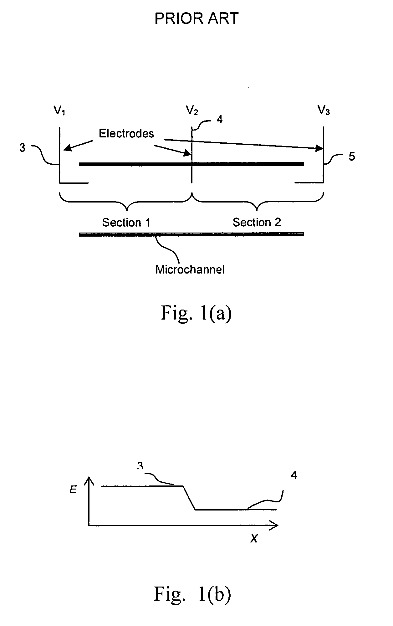
One major drawback to electric field gradient focusing is that the microchannel device tends to be difficult to construct and that it requires the control of voltage on an additional electrode, e.g. 4 of FIG. 1(a), that is used to apply the electric field gradient.
In addition, if electrodes are used to generate electric field gradients, unwanted chemical products will be generated electrochemically at the buffer-electrode interface.
One disadvantage with isoelectric focusing is that it is limited in application because it can only be used with analytes with an accessible pl.
Additionally, the concentration to which a protein can be focused with isoelectric focusing is severely limited due to the low solubility of most proteins at their pls.

Method used


Image

  • Fluidic temperature gradient focusing
  • Fluidic temperature gradient focusing
  • Fluidic temperature gradient focusing

Examples


Embodiment Construction

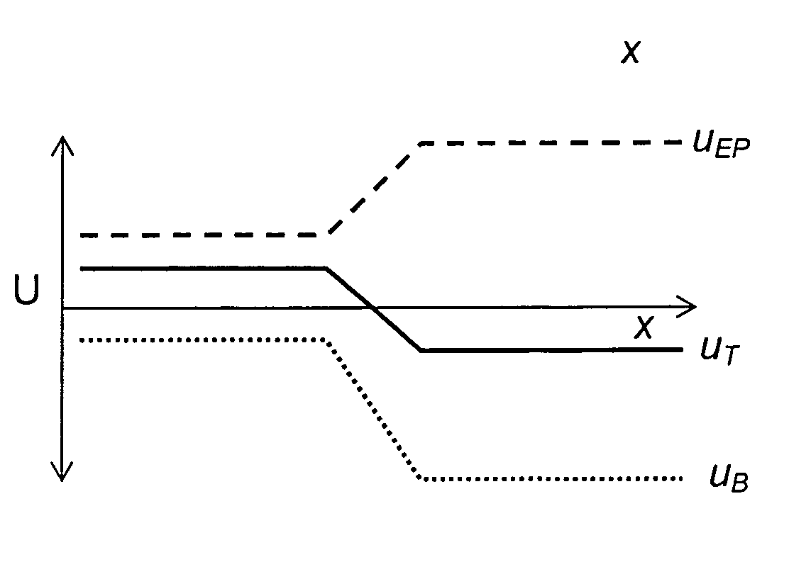
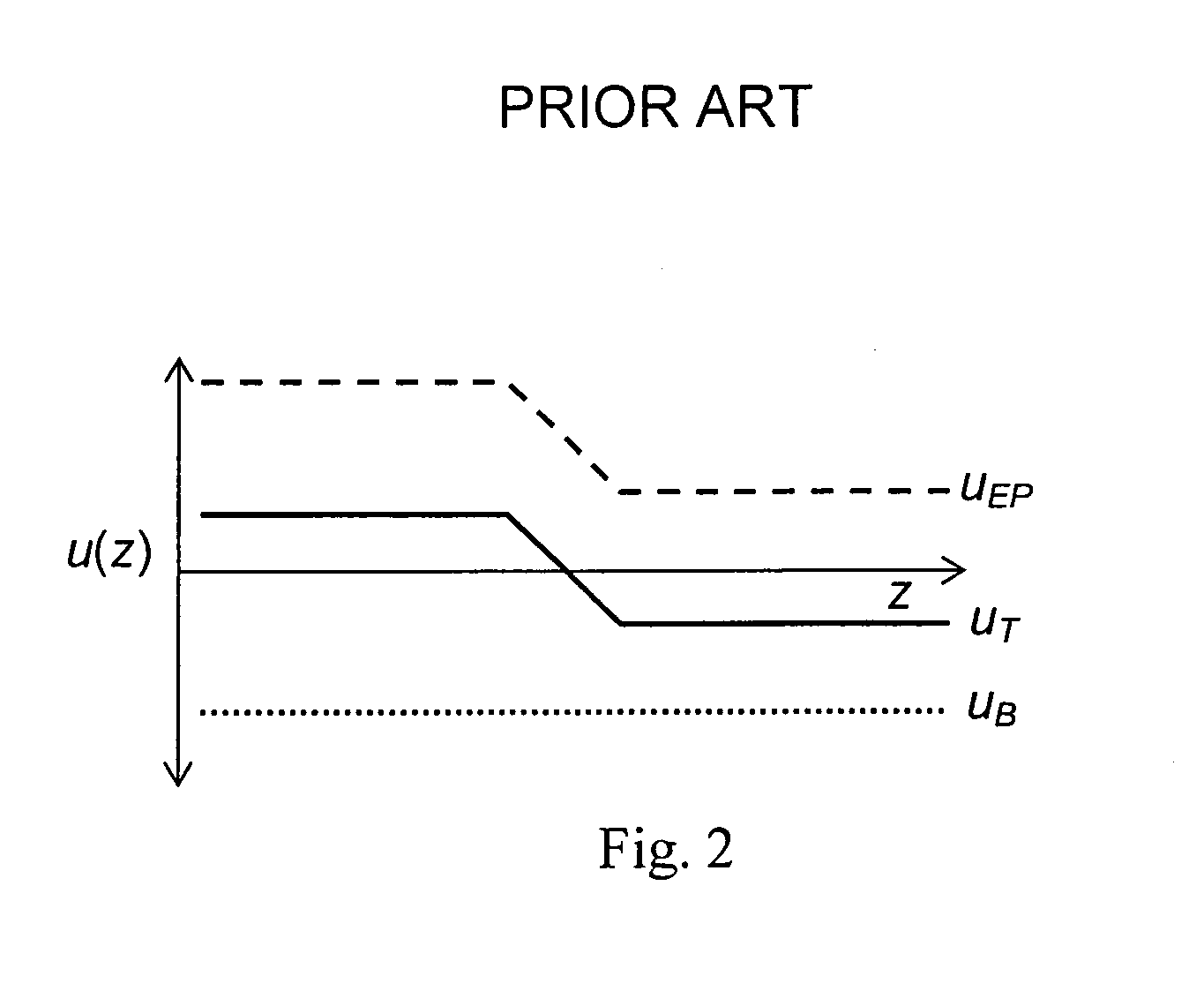
[0032]The present invention provides temperature gradient focusing of a sample in a fluidic device which includes a fluid conduit such as a channel or capillary tube. Temperature gradient focusing focuses analytes by balancing the electrophoretic velocity of an analyte against the bulk velocity of the buffer containing the analyte. If there is an appropriate gradient in the electric field, the total velocity of a given charged analyte, as determined by the sum of the bulk and electrophoretic velocities, can be set to zero at any point along the channel and all the analyte in the system is moved toward that point. However, in contrast to electric field gradient focusing where the electric field gradient is applied using a combination of electrodes and membranes, using temperature gradient focusing of the present invention, the necessary electric field gradient is produced by the application of a temperature gradient.

[0033]Further description of the present invention will now be made ...


PUM

PropertyMeasurementUnit
Lengthaaaaaaaaaa
Lengthaaaaaaaaaa
Temperatureaaaaaaaaaa

Abstract

A method and device are provided for concentrating and separating ionic species in solution within a fluidic device having a fluid conduit such as a channel or capillary. The concentration is achieved by balancing the electrophoretic velocity of an analyte against the bulk flow of solution in the presence of a temperature gradient. Using an appropriate buffer, the temperature gradient can generate a corresponding gradient in the electrophoretic velocity so that the electrophoretic and bulk velocities sum to zero at a unique point and the analyte will be focused at that point. The method and device may be adapted for use with a variety of analytes including fluorescent dyes, amino acids, proteins, DNA and to concentrate a dilute analyte.

Description

CROSS-REFERENCE TO RELATED APPLICATIONS[0001]This application claims benefit of the filing date of both copending Provisional Patent Application Nos. 60 / 307,691, filed on Jul. 25, 2001, and 60 / 323,404, filed on Sep. 19, 2001.STATEMENT REGARDING FEDERALLY SPONSORED RESEARCH[0002]This invention was made by employees of the United States Government and may be manufactured and used by or for the Government for governmental purposes without the payment of any royalties.FIELD OF THE INVENTION[0003]The present invention relates to a method for electrokinetic focusing of samples, and in particular, methods for electro-focusing samples in fluidic devices using electric field gradients.BACKGROUND OF THE INVENTION[0004]Over the past decade a great deal of research has been focused on the development of technology related to micro-total-analytical systems. This technology is based on the concept of a series of microfluidic channels also known as microchannels for the movement, separation, react...

Claims


Application Information

Patent Timeline
IPC IPC(8): G01N27/447G01N27/453
CPCG01N27/44795G01N27/44791
Inventor ROSS, DAVIDLOCASCIO, LAURIE E.
Owner GOVERNMENT OF THE US REPRESENTED BY THE SEC OF COMMERCE THE
Learn More