

Ion fragmentation in RF ion traps by electron capture with magnetic field
- Summary
- Abstract
- Description
- Claims
- Application Information
AI Technical Summary
Benefits of technology
Problems solved by technology
Method used
Image

Examples
Embodiment Construction
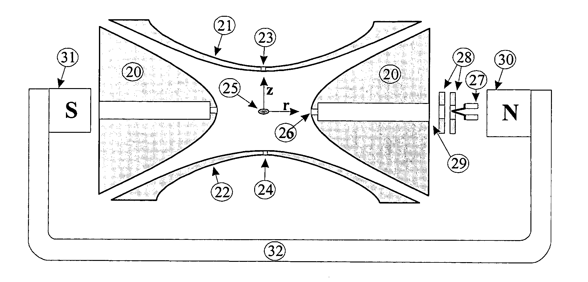
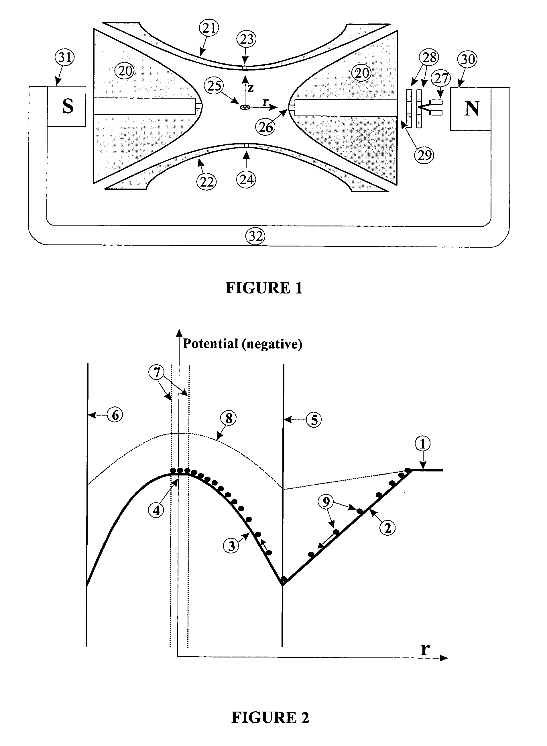
[0032]A favorable embodiment of the invention is illustrated in FIG. 1 and shows the magnetic guiding field for the electrons according to the invention with the two magnetic poles (39, 31).
[0033]An electrospray ion source outside the mass spectrometer is used to ionize the biomolecules. It is assumed here that a mixture of digest peptides of a larger protein is to be analyzed. The ions are guided in the usual way through a capillary and subsequent pressure stages with ion guides into the ion trap, where they are trapped. An initial mass spectrum provides an overview of the digest peptides. If it is required to analyze one or more peptides to establish their sequence of amino acids, the doubly charged ions of this peptide are isolated by normal means; this means that, after intentionally overfilling the ion trap, all ions which are not doubly charged ions of this peptide are ejected. The overfill is selected in such a way that, after the isolation, the correct number of ions for fra...
PUM
 Abstract
Description
Claims
Application Information