Inductively coupled dieletric barrier discharge lamp

a technology of dielectric barrier and discharge lamp, which is applied in the direction of water treatment parameter control, specific water treatment objectives, and separation processes, etc., can solve the problems of fluid irradiation at levels above or below the level needed for adequate treatment, and the connection between the transformer and the lamp body can be susceptible to fluid and corrosion, and achieve the effect of preventing ionization

Inactive Publication Date: 2017-01-19
ACCESS BUSINESS GRP INT LLC
View PDF8 Cites 0 Cited by
  • Summary
  • Abstract
  • Description
  • Claims
  • Application Information

AI Technical Summary

Benefits of technology

The patent text describes a new type of lamp assembly that can be used in a base station for wireless powering. The lamp assembly includes an inner tube and an outer tube with a discharge gap in between them. When a high voltage is applied, the lamp emits light through the outer tube and surrounding fluid. The base station includes an inductive primary and a control system to manage the performance of the lamp assembly. The lamp assembly also has an RF antenna for wireless communication with the base station. The use of the inductive primary as an RF reader / writer coil eliminates the need for a separate coil. The technical effects of this patent include improved wireless powering of lamps and increased efficiency of the base station.

Problems solved by technology

In use, the connection (e.g., electrical contacts) between the transformer and the lamp body can be susceptible to fluid and corrosion.
In addition, a major obstacle to the efficient treatment of fluid by prior art dielectric barrier gas discharge lamps is the irradiation of the fluid at levels above or below the level needed for adequate treatment.

Method used


Image

  • Inductively coupled dieletric barrier discharge lamp
  • Inductively coupled dieletric barrier discharge lamp
  • Inductively coupled dieletric barrier discharge lamp

Examples


first embodiment

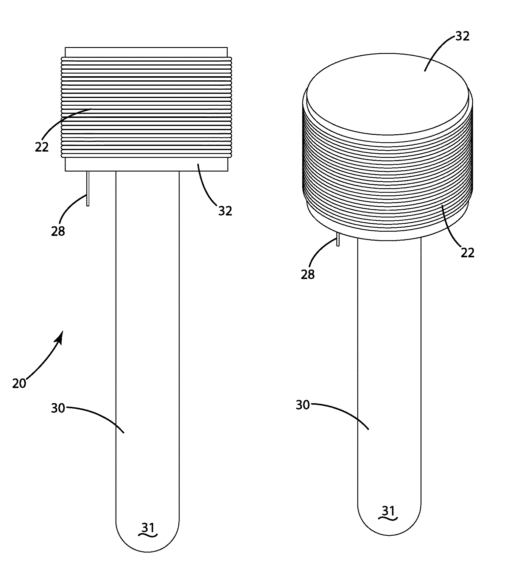
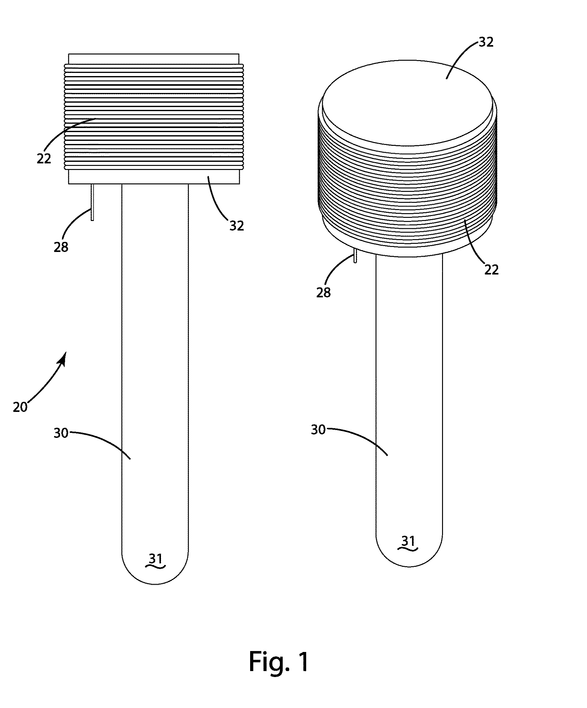
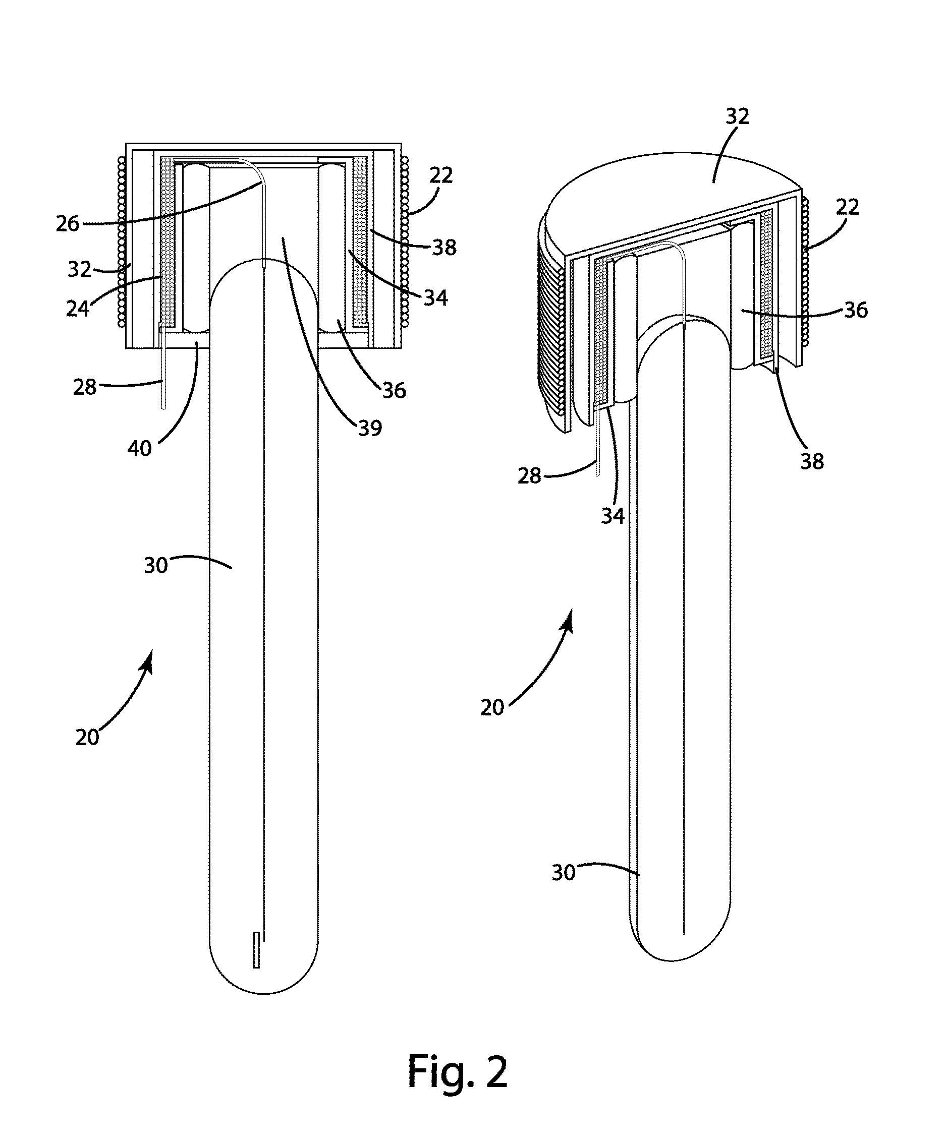
[0036]Referring now to FIGS. 1-3, a lamp assembly is illustrated and generally designated 20. The lamp assembly 20 includes an inductive secondary or secondary coil 24 adapted to receive wireless power from a nearby inductive primary or primary coil 22, a first electrode 26 electrically coupled to the secondary coil 24, a second electrode 28 electrically coupled to the secondary coil 24, and a dielectric barrier discharge lamp body 30. The secondary coil 24 can include any element adapted to generate an internal electrical current in response to an external time-varying electromagnetic field. For example, the secondary coil 24 can be formed of a conducting element wound one or more times around an axis, while in other embodiments the secondary coil 24 can include a stamped or printed conductive winding in a non-conductive substrate. The first and second electrodes 26, 28 can be an extension of the secondary coil 24, or can be separately formed and electrically coupled to respective...

third embodiment

[0048]Operation of the third embodiment can be described in conjunction with the flowchart of FIG. 13. When water flow is detected by the water flow rate sensor 50 in step 102, the microcontroller 44 causes power to be delivered to the primary coil 22 at step 104. The level of power to be delivered at step 102 is determined by the microcontroller 44 by formula or through the use of a look-up table substantially as set forth above. At step 106, the microcontroller 44 verifies operation of the lamp through the lamp sensor 108. If the lamp is verified to be on and at the correct intensity, the lamp pulse driver 46 will continue to deliver the same power to the primary coil 22. If an adjustment is needed at step 108 based on the output of the lamp sensor 48, the water flow rate sensor 50 and / or the water quality sensor 92, the system may also adjust the power delivery to the primary coil 22. For example, a lower turbidity can require lower ultraviolet lamp intensities, while a higher tu...

fourth embodiment

[0051]Operation of the fourth embodiment can be further described in conjunction with the flowchart of FIG. 15. When water flow is detected in step 130, optionally via a water flow rate sensor 50, the primary coil 22 operates in a communications mode to read wireless data from the memory tag 120 associated with (or contained within) the secondary lamp assembly 20 at step 132. As noted above, the wireless data can include the cumulative prior operational use data and a unique lamp serial number. At step 134, the primary coil 22 can operate in a power supply mode under control of the microcontroller 44 and lamp driver 46 to provide power to the secondary coil 24. The amount of power applied at step 134 can vary from application to application, and can be based at least in part on the fluid flow rate and the cumulative prior operational data to achieve a desired lamp intensity. At step 136, the microcontroller 44 can evaluate or read the output of the lamp sensor 48, the water flow rat...


PUM

PropertyMeasurementUnit
wavelengthsaaaaaaaaaa

Abstract

A dielectric barrier discharge lamp assembly for a fluid treatment system. The lamp assembly can include an inductive secondary, first and second electrodes coupled to the inductive secondary, and a lamp including a dielectric barrier interposed between the first and second electrodes. The dielectric barrier can define a discharge chamber including a discharge gas, and one of the first and second electrodes can extend within the discharge chamber. The inductive secondary can be adapted to receive power from a nearby inductive primary to promote a dielectric barrier discharge in the discharge chamber. The resulting dielectric barrier discharge can generate ultraviolet light for the treatment of air or water, or for other applications.

Description

BACKGROUND OF THE INVENTION[0001]The present invention relates to dielectric barrier discharge lamps. In particular, the present invention relates to dielectric barrier discharge lamps for use in fluid treatment systems, luminary systems and other applications.[0002]Dielectric barrier discharge lamps are generally known and are used in a variety of applications where electromagnetic radiation of a particular wavelength is desired. For example, some applications include wastewater treatment and / or the disinfection of drinking water. These applications can require ultraviolet radiation with wavelengths between about 100 nm and 280 nm. Other applications include generating visible light for general lighting, which can require wavelengths between about 380 nm and 750 nm.[0003]Dielectric barrier discharge lamps can generally be of any form. One of the simplest forms of dielectric barrier discharge lamps includes an outer tube and a coaxial inner tube forming an annular discharge chamber ...

Claims


Application Information

Patent Timeline
Patent Type & Authority Applications(United States)
IPC IPC(8): C02F1/32C02F1/28
CPCC02F1/325C02F1/283C02F2201/326C02F2201/3222C02F2303/04C02F2209/11C02F2209/06C02F2209/02C02F2209/40C02F2209/006B01D53/74C02F1/32H01F38/14H01J5/54H01J5/62H01J65/046C02F2201/3223C02F2209/005C02F2209/008H01J65/04H01J65/048
Inventor VECZIEDINS, KARLISMILES, MICHAEL E.SCHWANNECKE, JOSHUA K.MEEKHOF, DAVID A.SQUIRES, DONOVAN L.STONER, WILLIAM T.NORCONK, MATTHEW J.BYLSMA, RICHARD B.LILLEY, MATTHEW J.
Owner ACCESS BUSINESS GRP INT LLC
Why Eureka
Try Eureka