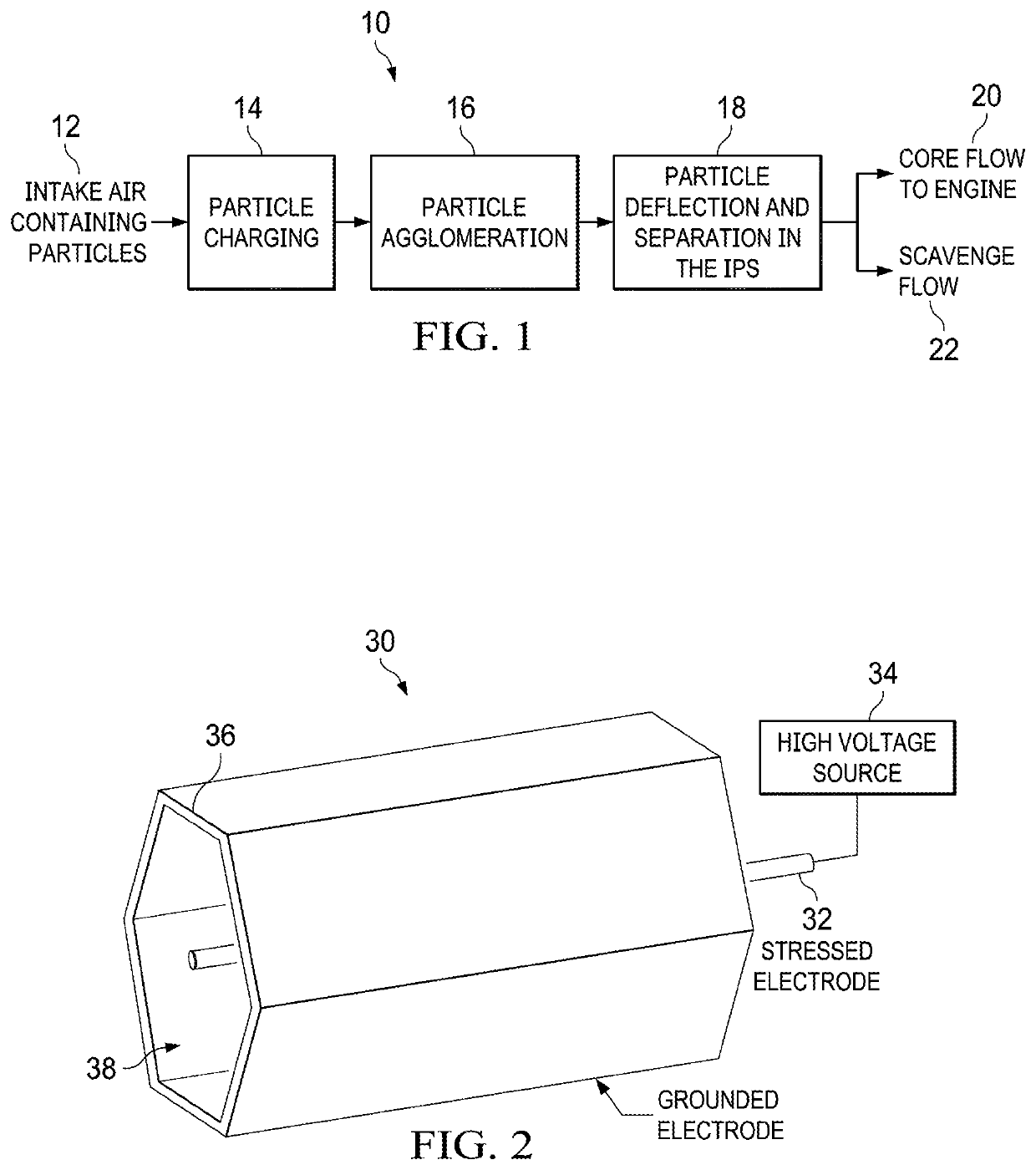
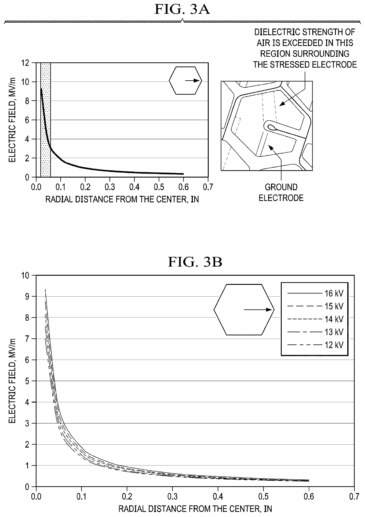
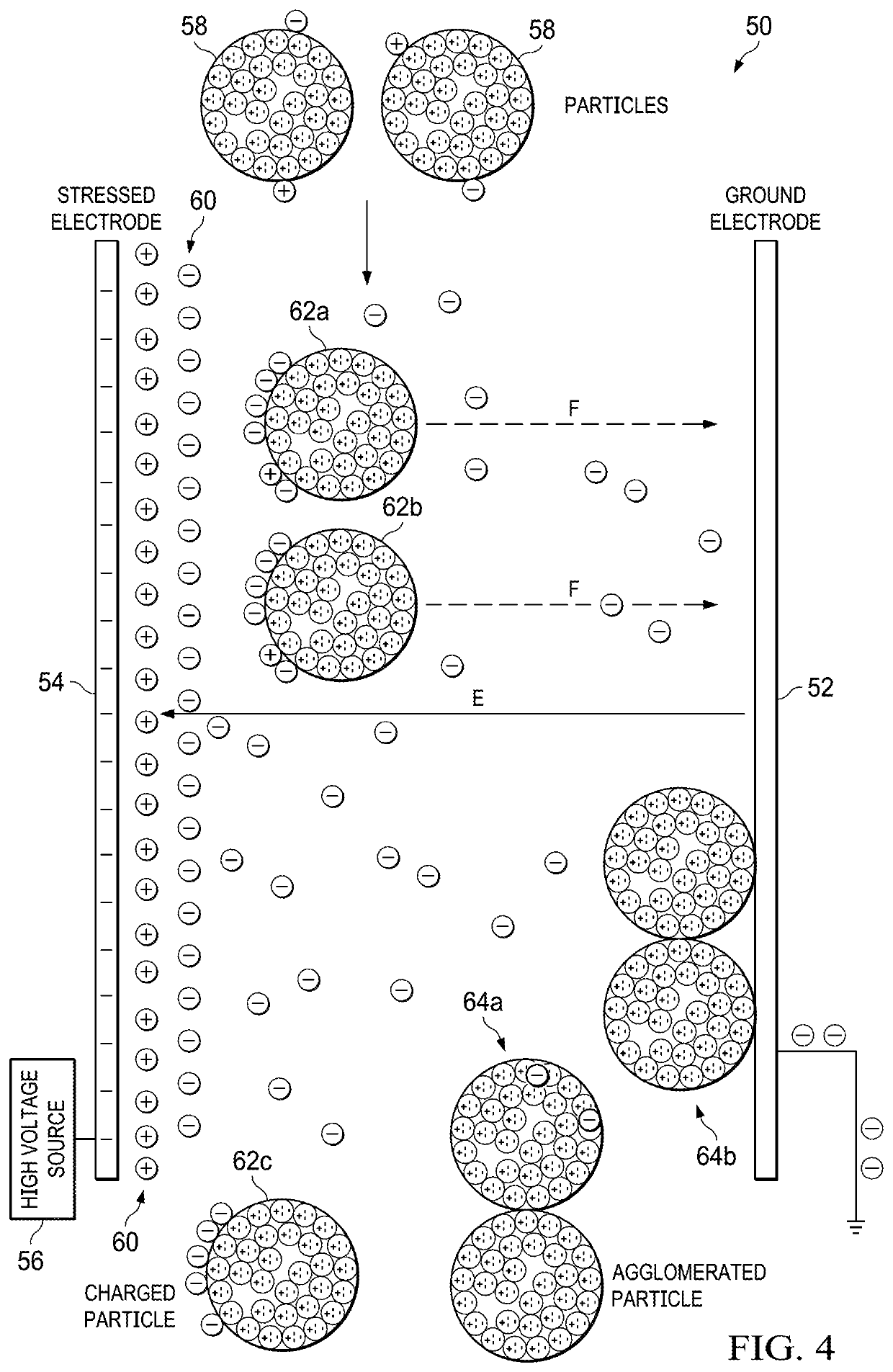
[0087]Prolonged operation of the charger tube can result in accumulation of particles along the tube surface, which can reduce charging effectiveness and eventually lead to unstable operation due to sparking. The present invention includes a means to reduce such accumulation of particles. Application of negatively biased AC voltage (12-16 kV peak, peak-peak change of 1 kV, 10 Hz-60 kHz) to the stressed electrode is the preferred embodiment to reduce accumulation of particles in the charger tube connected to a negative voltage source. Therefore another advantage of the present invention is the application of negatively biased AC voltage to enable long term operation of electrostatic charging devices. An approach to prevent sparking in the charger tube is to internally line the ground electrode with a dielectric film and / or to encapsulate the stressed electrode in a dielectric tube. The dielectric material can be any material with dielectric strength greater than 3 MV / m. These materials include plastics (Teflon, PEEK, etc.), quartz, and ceramics (oxides, carbides, nitrides, etc). This dielectric-lined charger tube can be operated in the pulsed DC mode (12-16 kV peak with <1 ms pulse width) or biased AC mode (12-16 kV peak, peak-peak change of 1 kV, 10 Hz-60 kHz) for electrostatic charging of particles.
[0089]For turbine engine applications a single charger tube may be used or multiple charger tubes may be arranged, such that the particles in the large intake air volume / flow can be sufficiently accommodated and charged, according to the aforementioned specifications. These charger tubes can be packed together to form a bundle similar in shape to the annular opening of the IPS. These charger tubes can have any cross-sectional shape such as a circular, hexagonal, square, triangular, rectangular, etc. and can be arranged in any layout but they should provide the greatest open area for flow to ensure low pressure drop in intake air flow for turbine engine applications. Unlike circular cross-section, other cross-sections such as circular, square, triangular, rectangular, etc. can be packed together to have common or shared walls, thereby reducing material required to build them and the total weight. A comparison between circular and hexagonal cross-section geometries shown in FIG. 6 outlines the multiple benefits that the hexagonal cross-section tube geometry provides. The hexagonal cross-section is represented as a honeycomb structure with common or shared walls. The main benefits are greater open surface area and lesser weight. Higher open surface area results in lower pressure drop in intake airflow and lesser weight ensures that more engine power is available for useful work. The charger tube with hexagonal cross-section thus provides major benefits over circular cross-section charger tube in turbine engine applications.
[0091]Air containing unipolarly charged dust particles from the Particle Charging Stage 1 can be flown into the Particle Agglomeration Stage 2. The goal of this Stage is to agglomerate the incoming charged dust particles and thereby enhance IPS separation efficiency, since the IPS separates larger particles more efficiently than finer particles. The Particle Agglomeration Stage 2 can accomplish agglomeration by the use of electric fields and / or by the use of turbulent mixing features. The electric field is distinct from the one used in Particle Charging Stage 1. One embodiment of the use of electric field is shown in FIG. 7. A charging device 70 shows an electric field 72 that is maintained between an inner surface 74 and outer surface 76 by the application of high voltage 78. The inner surface 74 and outer surface 76 serve as electrodes to generate the electric field 72 for promotion of agglomeration. It is to be noted that there is no electrical discharge in this device since the electric field is maintained below the dielectric strength of air to prevent ionization. For an inner surface of diameter 1.325″ and an outer surface of diameter 3″, voltages up to 41 kV can be applied without causing an electrical discharge. A constant electric field can be applied to cause the charged particles to move transverse to the air flow, i.e., towards either of the surfaces as they flow in the axial direction. During the motion of the charged particles in the electric field, they can collide, stick to each other, and agglomerate. An oscillating (10-500 Hz, 41 kV peak) or pulsed electric field (<1 ms peak width and 41 kV peak) can also be applied to cause the particles to oscillate or move spontaneously in the direction transverse to air flow. The induced oscillations are of different amplitudes for different particle sizes resulting in increased probability of collision of charged particles, thereby promoting their agglomeration.
[0092]Another embodiment of Particle Agglomeration Stage 2 is the generation of turbulence in the airflow containing charged dust particles to promote interparticle collision and agglomeration. FIGS. 8A and 8B shows an agglomeration device 80, that shows an end-view (FIG. 8A) and a cross-sectional side view (FIG. 8B) of the agglomeration device 80. FIG. 8A shows trapezoidal mixing tabs 82a,b,c,d installed along the outer wall 84 in relation to the inner surface 86. FIG. 8B shows a pair of arrays 86a,b that have mixing tabs 82 placed at 90° with respect to each other in the opening 88 of the agglomeration device 80 or portion of the device. The tabs 82a,b,c,d are inclined at 30° relative to the tube walls 84, 86 in the direction of the flow within the opening 88. FIG. 8C shows some preferred specifications and dimensions for mixing tabs with trapezoidal geometry. While the mixing tabs 82 are depicted as being trapezoidal, the mixing tabs 82 can have any shape, e.g., square, rectangular, triangular, polygonal, circular, oval, etc. FIG. 8D shows different types of vortices formed by a tab 82 in relation to the fluid flow. FIG. 8D shows that various vortices are generated in the airflow to promote mixing by the mixing tab 82, these different vortices are, e.g., hairpin vortices 90, reverse vortices 92, transverse vortices 94, primary counter-rotating vortex pairs 96 (CVP), primary counter-rotating vortex pairs 98, etc. The mixing is found to occur in three different scales: micro-mixing due to diffusive transfer, meso-mixing due to velocity fluctuations in eddies, and macro-mixing by large scale flows. For efficient mixing of micron-sized bipolarly charged particles, meso- and macro-mixing are the relevant scales. The hairpin vortices contribute majorly to meso-mixing and the tab geometry contributes to macro-mixing. There are two types of mixing in the tab wake: (i) mixing between the ambient fluid and the wake, which is the region spanned by the CVP and hair pin structures, and (ii) mixing inside the wake. The mixing between the wake and the ambient air flow is attributed to hairpin vortices and in the near-wake region is due to the CVP. The vortex mixing of differently charged particles results in increased probability of collisions between the oppositely charged particles, which are drawn to each other by their opposing charges. The greater number of collisions results in a greater degree of agglomeration between charged particles. A drawback of use of turbulent mixing is pressure loss in the intake airflow and therefore a tradeoff study is recommended for selection of the mixing tab dimensions and inclination, layout pattern and inter-tab distance. Another embodiment of the Particle Agglomeration Stage 3 (100) is the combination of electric field 72 formed by high voltage power supply 78 and mixing tabs 82 in the same volume as shown in the end view of FIG. 8E, that includes outer wall 84 and inner wall 86.
[0094]Air containing the charged and agglomerated dust particles is then flown into the Particle Deflection and Separation stage. This stage is integrated into an inertial separation device 200 such as the IPS as shown in FIG. 9. The outer surface 202 of the IPS 200 is maintained at a positive potential by connecting it to a high voltage power supply 204. It is to be noted that there is no electrical discharge in this stage since the electric field is maintained below the dielectric strength of air to prevent ionization. Negatively charged particles entering the field experience an electrostatic force of attraction towards the outer surface 202 and are deflected towards the scavenge flow path 206. Alternatively, the inner surface 208 can be maintained at a negative potential, while the outer surface 202 is grounded, or vice versa. In this case, the negatively charged particles would be repelled away from the inner surface 208 and towards the scavenge flow path 206. Alternatively, if the particles entering the IPS 200 carry predominantly positive charge, the outer surface 202 can be maintained at a negative potential while the inner surface 208 is grounded or the inner surface 208 can be maintained at a positive potential, while the outer surface 202 is grounded. The whole surface or part of the inner and outer surfaces (208, 202) of the IPS 200 can serve as the deflection electrodes, wherein one of them is maintained at a high potential while the other is grounded. The electrode maintained at a high potential should be electrically isolated from the rest of the IPS 200 or the engine. Electrical isolation can be achieved by use of dielectric materials with dielectric strength greater than that of air such as PEEK or ceramics such as carbides, nitrides or oxides. The goal of this stage is to deflect the charged particles into the scavenge flow 206 using an electric field thereby reducing the number of particles flowing into the core flow 210, which results in an improvement in the IPS 200 separation efficiency.
[0096]As shown in FIG. 10, a device 300 used to create the biased AC waveform is used with the present invention (see FIG. 11) and is generated by combining a negative DC power supply 302 with a high voltage AC transformer 304. The lead of the negative DC power supply 302 is connected to the ground connection of the secondary coil of the high voltage transformer 304. For example, the negative DC power supply is set to 12.5 kV, while the high voltage transformer is set to oscillate at 2.5 kV peak-peak. The resulting waveform oscillated between 10 kV and 15 kV and is labeled as Neg AC in FIG. 11. The negatively biased AC waveform is used to drive the charger tubes in the Particle Charging Stage 1. When no DC power supply is used in the circuit, the typical AC waveform is obtained that oscillates between 15 kV and −15 kV. The minimum voltage required for ionization in the charger tube (0.612″ side hexagonal cross-section tube with 0.039″ diameter rod; 6″ long) is about ±5.2 kV. The shaded region in FIG. 11 indicates the voltages that exceed the ionization voltage. The biasing of the AC waveform ensures that the output voltage is always greater than the ionization voltage, whereas the output voltage for the entire AC cycle is not within the ionization region. Therefore, during a part of the AC cycle, the ions and electrons are not generated, whereas they are generated during the entire cycle of the biased waveform (Neg AC). Charging of dust particle is improved because there is continuous generation of ions and electrons during the entire cycle. If the negative DC power supply 302 in FIG. 10 is replaced with a positive DC power supply, the positively biased waveform labeled as Pos AC is obtained. The positively biased AC waveform can be used in the Agglomeration Stage 2 and the Deflection Stage 3.