Electrical short tracing apparatus and method

a short-circuit tracing and electrical technology, applied in short-circuit testing, line-transmission details, instruments, etc., can solve the problems of high current pulse generation, difficulty in both tracing and isolating short-circuits, etc., and achieve the effect of low cos

Inactive Publication Date: 2006-04-18
CARPENTER KEVIN
View PDF19 Cites 31 Cited by
  • Summary
  • Abstract
  • Description
  • Claims
  • Application Information

AI Technical Summary

Benefits of technology

[0028]The short circuit testing apparatus of the invention, hereafter referred to as the “vehicle short circuit tester”, “circuit tester”, or simply “tester”, preferably comprises both a means for generating a test signal on a shorted circuit to facilitate tracing the short, and a means for generating an audible output in response to significant changes in the characteristics of the short circuit. The tester provides a selectable constant current within the bounds of the circuit under test, which facilitates tracing the current path to locate the short. It does not, however, generate intermittent high current pulses which pose difficulty in both the tracing and isolating of short circuits. The audible output of the tester is generated in response to significant changes in the current characteristics of the short without requiring that overall circuit current (i.e. to short and other loads) drop to a zero, or near zero, current level.
[0035]An aspect of the invention is to provide for generating a test signal which facilitates rapid tracing of short circuits.
[0037]Another aspect of the invention is to generate a test signal whose output current can be readily selected to suit the current capacity of the circuit under test.
[0042]A still further aspect of the invention is to provide a low cost short circuit testing device that does not necessitate utilizing a computer for either circuit control or signal processing.

Problems solved by technology

It does not, however, generate intermittent high current pulses which pose difficulty in both the tracing and isolating of short circuits.

Method used


Image

  • Electrical short tracing apparatus and method
  • Electrical short tracing apparatus and method
  • Electrical short tracing apparatus and method

Examples


Embodiment Construction

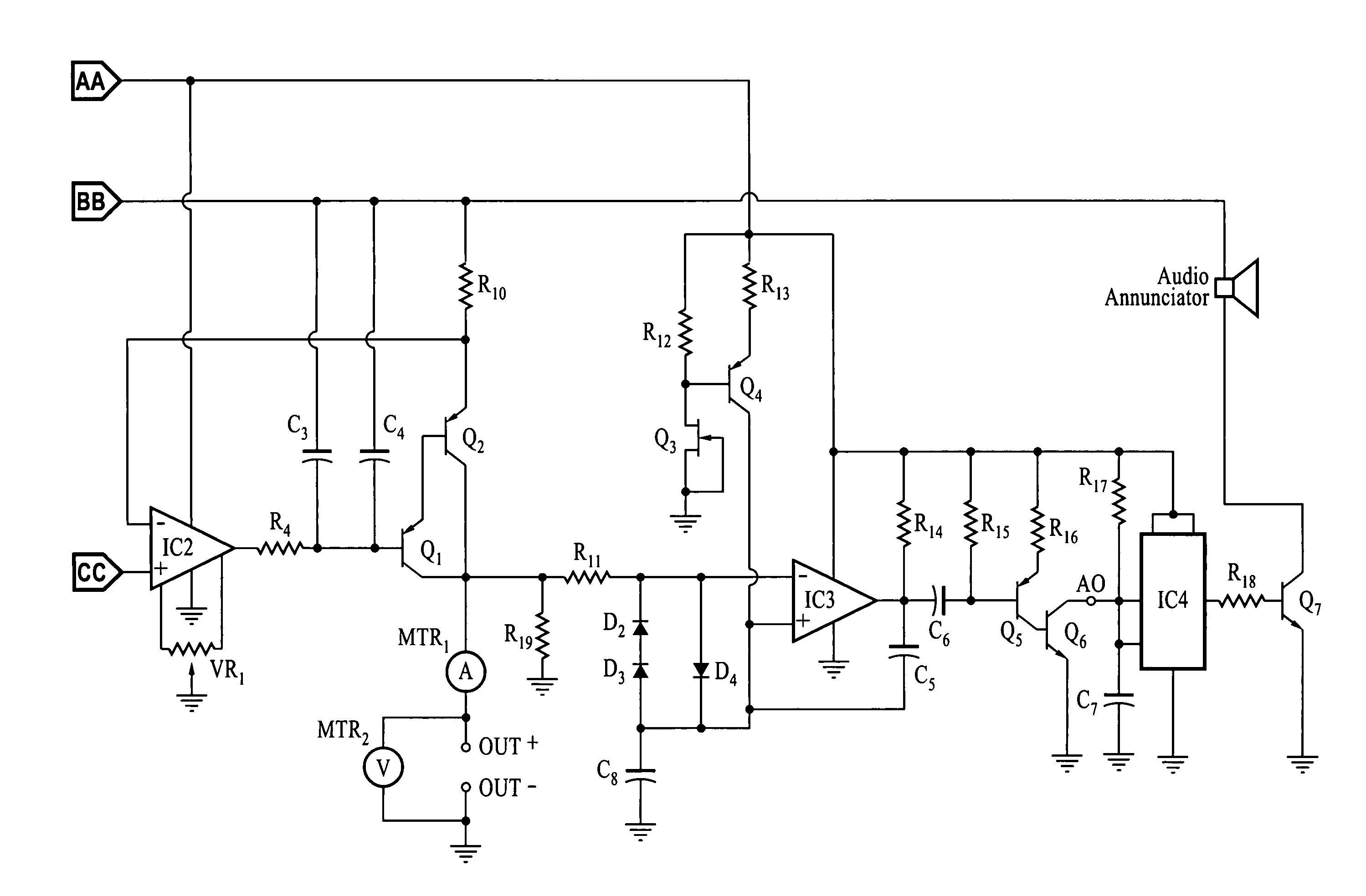
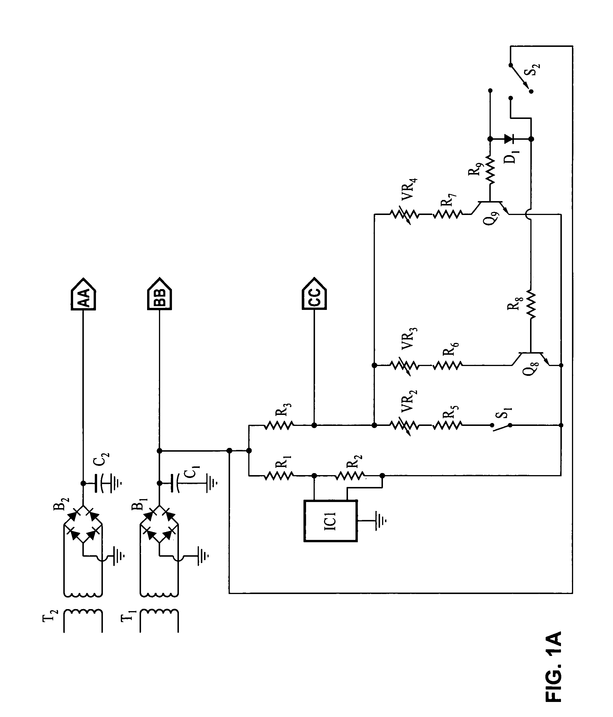
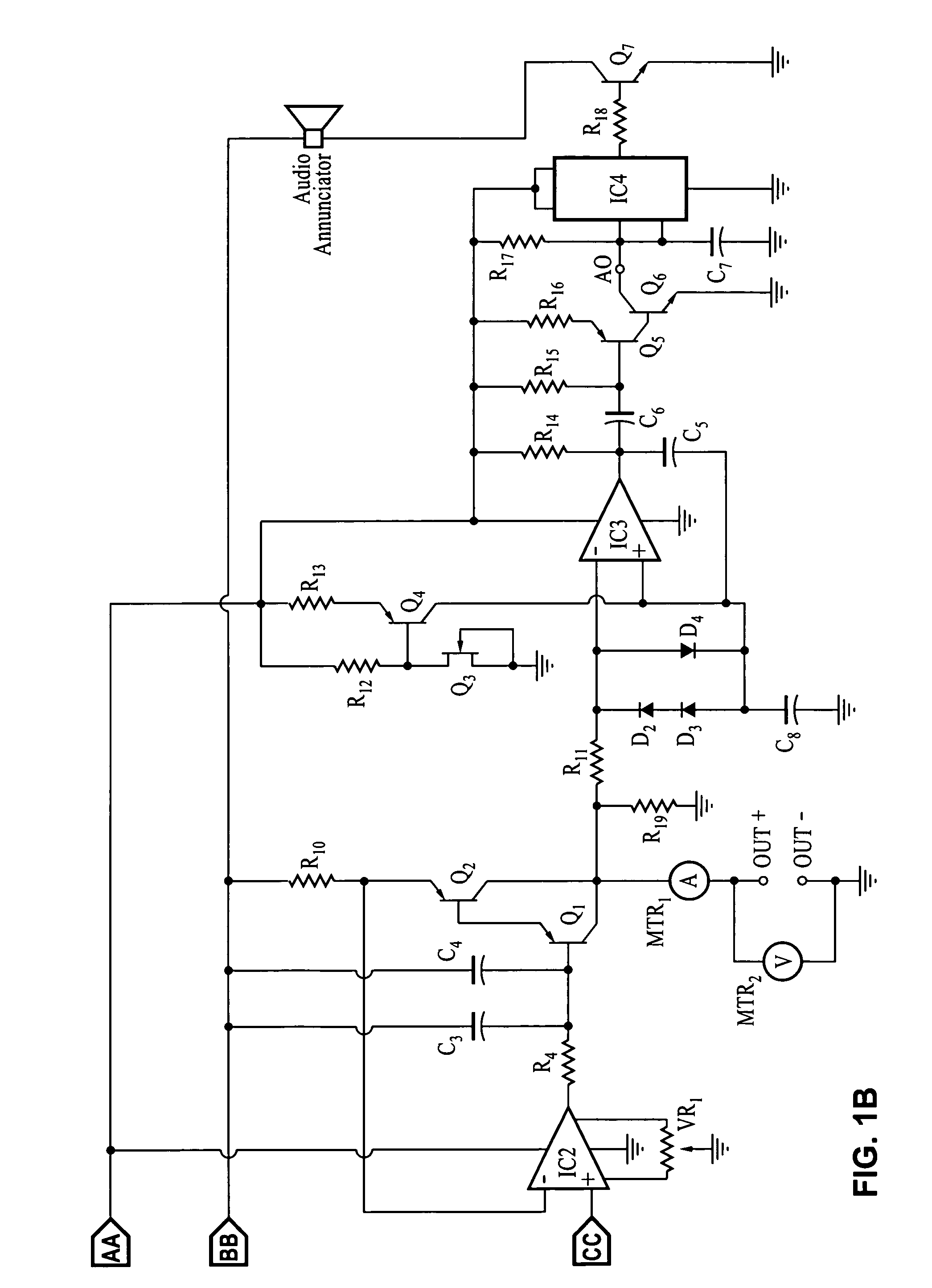
[0046]Referring more specifically to the drawings, for illustrative purposes the present invention is embodied in the apparatus generally shown in FIG. 1A and FIG. 1B. It will be appreciated that the apparatus may vary as to configuration and as to details of the parts, and that the method may vary as to the specific steps and sequence, without departing from the basic concepts as disclosed herein.

[0047]The short tracing device of the invention generally performs three major functions, (1) the sourcing of a predetermined “stiff” and consistently traceable current output (i.e. selectable within the range of 1–10 Amperes for 12V automotive circuits); the detection of a substantial change in short circuit conductance registered as a sufficient voltage change arising at the applied current level. (i.e. predetermined voltage increase within the range of from 0.2 volts to 1.0 volts); and the audible annunciation of the substantial conductance change.

[0048]The short testing device has an o...


PUM


Abstract

A vehicle testing apparatus and method which facilitates tracing and isolating of short circuits. The tester preferably provides a user-selected constant current level (i.e. 1, 3 and 6 amperes) for driving a vehicle short under test at a constant current level compatible with the circuit. Any significant changes in the conductance of the vehicle short under test are registered in response to circuit voltage changes. An annunciator is activated in response to sudden significant conductance changes (preferably conductance decreases) which exceed a threshold level. Annunciation (preferably including audio output) allows the operator to immediately correlate movements of specific regions of wiring, or other circuit elements, with changes in the detected short conductance for the shorted circuit being tested. By way of example and not of limitation the tester may be implemented inexpensively with low cost analog circuitry, and does not require incorporating a microcontroller.

Description

CROSS-REFERENCE TO RELATED APPLICATIONS[0001]Not ApplicableSTATEMENT REGARDING FEDERALLY SPONSORED RESEARCH OR DEVELOPMENT[0002]Not ApplicableINCORPORATION-BY-REFERENCE OF MATERIAL SUBMITTED ON A COMPACT DISC[0003]Not ApplicableNOTICE OF MATERIAL SUBJECT TO COPYRIGHT PROTECTION[0004]A portion of the material in this patent document is subject to copyright protection under the copyright laws of the United States and of other countries. The owner of the copyright rights has no objection to the facsimile reproduction by anyone of the patent document or the patent disclosure, as it appears in the United States Patent and Trademark Office publicly available file or records, but otherwise reserves all copyright rights whatsoever. The copyright owner does not hereby waive any of its rights to have this patent document maintained in secrecy, including without limitation its rights pursuant to 37 C.F.R. § 1.14.BACKGROUND OF THE INVENTION[0005]1. Field of the Invention[0006]This invention per...

Claims


Application Information

Patent Timeline
Patent Type & Authority Patents(United States)
IPC IPC(8): G01R31/02G01R31/08G08B21/00
CPCG01R31/025G01R31/006G01R31/52
Inventor CARPENTER, KEVIN
Owner CARPENTER KEVIN
Why Eureka
Try Eureka