
Low pin testing system

a testing system and low pin technology, applied in the direction of measuring devices, electric connection testing, instruments, etc., can solve the problems of unlocked terminals eventually moving out of contact with their mates, requiring expensive and time-consuming debugging to determine, and affecting the efficiency of unlocked terminal detection

Inactive Publication Date: 2006-04-18
FARGO ASSEMBLY
View PDF18 Cites 17 Cited by
  • Summary
  • Abstract
  • Description
  • Claims
  • Application Information

AI Technical Summary

Benefits of technology

[0009]In view of the foregoing disadvantages inherent in the known types of low pin testers now present in the prior art, the present invention provides a new low pin testing system construction wherein the same can be utilized for efficiently detecting unlocked terminals within an electrical connector.
[0015]A second object is to provide a low pin testing system for efficiently and reliably detecting unlocked terminals within an electrical connector.
[0016]Another object is to provide a low pin testing system that provides a low cost alternative to micro switch probes for unlocked terminal testing.

Problems solved by technology

However, an unlocked terminal will eventually move out of contact with its mate due to shipping, handling, vibration or other force.
When an unlocked terminal moves out of contact with its mate, this not only causes a breakdown of the machinery that the connector is used within but also requires expensive and time consuming debugging to determine the cause of the problem.
While conventional continuity testers may be suitable for the particular purpose to which they address, they are not as suitable for efficiently detecting unlocked terminals within an electrical connector.
Conventional continuity testers utilize electrical continuity to test for unlocked terminals which can result in unlocked terminals passing the continuity test and failing later in the end application.

Method used


Image

  • Low pin testing system
  • Low pin testing system
  • Low pin testing system

Examples


Embodiment Construction

A. Overview

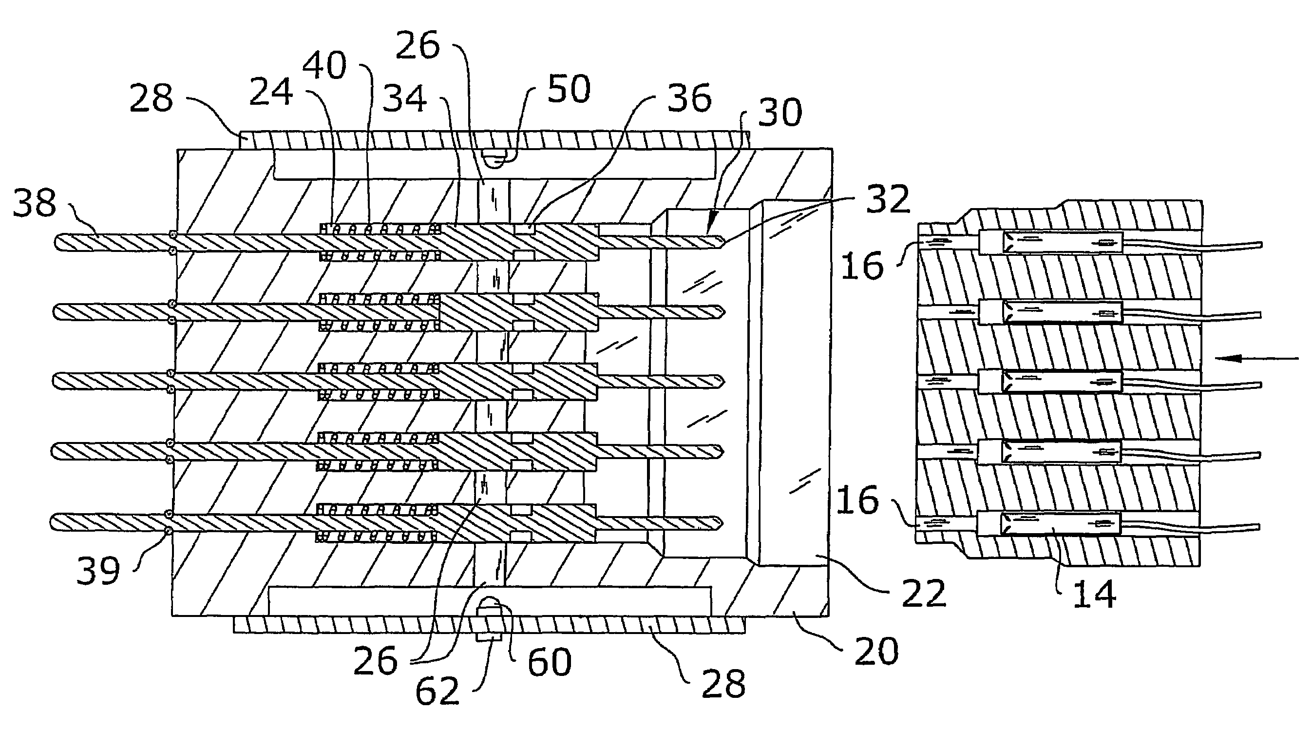
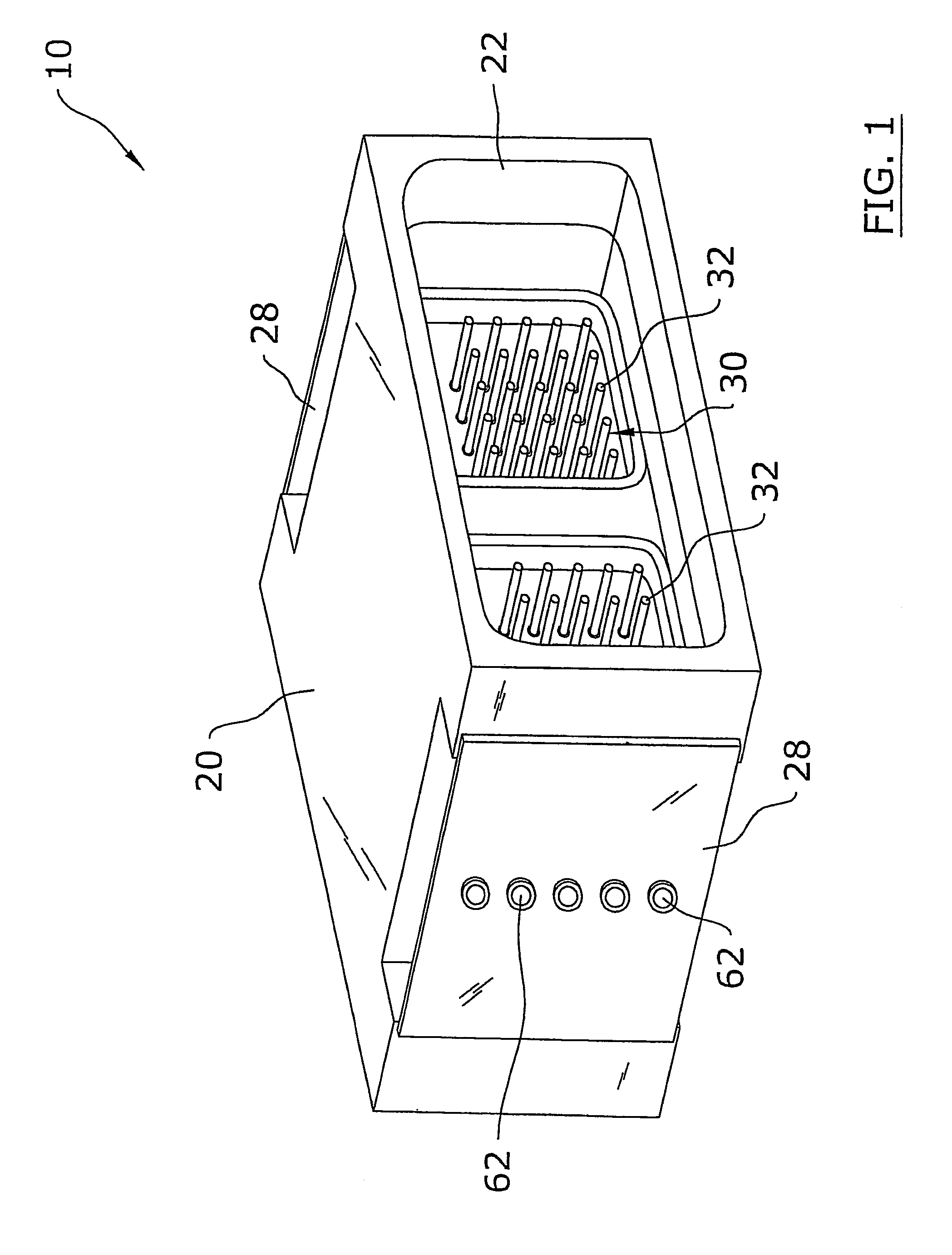
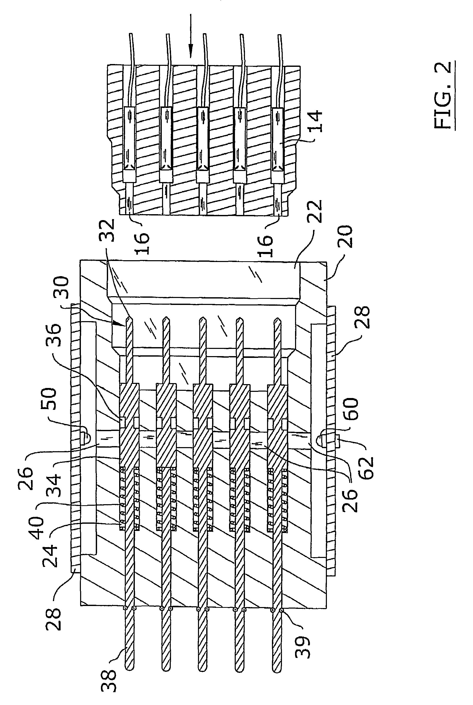
[0036]Turning now descriptively to the drawings, in which similar reference characters denote similar elements throughout the several views, FIGS. 1 through 13 illustrate a low pin testing system 10, which comprises a housing 20 with a receiver opening 22 for removably receiving an electrical connector 12 to be tested, a plurality of probe passages 24 within the housing 20, a plurality of testing probes 30 slidably positioned within the housing 20 in a biased manner each having an engaging end 32 extending into said receiver opening 22 and corresponding to a terminal within the electrical connector 12, a plurality of light emitters 50 for illuminating light through corresponding light passages 26, and a plurality of light receivers 60 at the opposite end of the light passages 26. The light passages 26 extend substantially transverse through a row of the probe passages 24 and the testing probes 30 each include a cutout 36 that allows the light to pass through the testing p...


PUM


Abstract

A low pin testing system for efficiently detecting unlocked terminals within an electrical connector. The low pin testing system includes a housing with a receiver opening for removably receiving an electrical connector to be tested, a plurality of probe passages within the housing, a plurality of testing probes slidably positioned within the housing in a biased manner each having an engaging end extending into said receiver opening and corresponding to a terminal within the electrical connector, a plurality of light emitters for illuminating light through corresponding light passages, and a plurality of light receivers at the opposite end of the light passages. The light passages extend substantially transverse through a row of the probe passages and the testing probes each include a cutout that allows the light to pass through the testing probes when the testing probes are moved from engagement with the terminals of an electrical connector.

Description

CROSS REFERENCE TO RELATED APPLICATIONS[0001]Not applicable to this application.STATEMENT REGARDING FEDERALLY SPONSORED RESEARCH OR DEVELOPMENT[0002]Not applicable to this application.BACKGROUND OF THE INVENTION[0003]1. Field of the Invention[0004]The present invention relates generally to low pin testing devices and more specifically it relates to a low pin testing system for efficiently detecting unlocked terminals within an electrical connector.[0005]2. Description of the Related Art[0006]When manufacturing a wire harness, it is important that there are no unlocked terminals (referred to as “low pins”) within the electrical connectors. An unlocked terminal within an electrical connector may pass conventional continuity testing and may even work initially within the end application. However, an unlocked terminal will eventually move out of contact with its mate due to shipping, handling, vibration or other force. When an unlocked terminal moves out of contact with its mate, this n...

Claims


Application Information

Patent Timeline
IPC IPC(8): G01R31/02
CPCG01R31/045H01R43/20G01R31/308G01R31/69
Inventor BERGAN, RONALD O.BAHLS, LEE R.
Owner FARGO ASSEMBLY
Learn More