Voltage detector

a voltage detector and detector technology, applied in the field of electronic devices, can solve problems such as a large amount of power consumption

Inactive Publication Date: 2006-04-18
XILINX INC
View PDF13 Cites 79 Cited by
  • Summary
  • Abstract
  • Description
  • Claims
  • Application Information

AI Technical Summary

Problems solved by technology

Although useful, a band-gap regulated PUR circuit has several disadvantages, mainly it consumes a lot of power.

Method used


Image

  • Voltage detector
  • Voltage detector
  • Voltage detector

Examples


Embodiment Construction

[0019]While the specification concludes with claims defining the features of the invention that are regarded as novel, it is believed that the invention is better understood from a consideration of the following description in conjunction with the drawing figures.

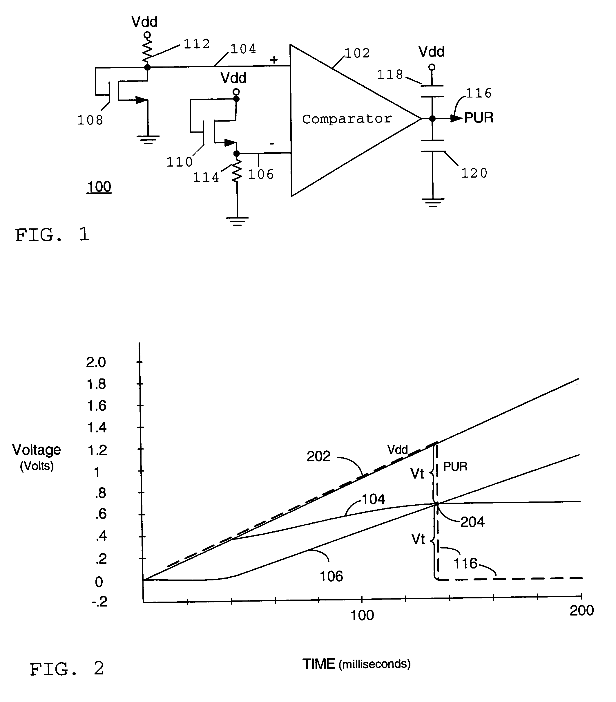
[0020]Referring to FIG. 1, there is shown a reset circuit 100 in accordance with one embodiment of the invention. Circuit 100 includes a comparator 102 having a first input 104 and a second input 106. Coupled to the first input 104 is a first diode-connected transistor 108 and coupled to the second input 106 is a second diode-connected transistor 110. A diode-connected transistor is one in which the gate is connected to the drain and is made to behave like a diode under certain circumstances. In an alternative embodiment, the diode-connected transistors 108 and 110 are replaced by diodes.

[0021]Both of the transistors 108 and 110 have current limiting resistors 112 and 114 coupled to them as shown. Comparator 102 includes a ...


PUM


Abstract

A voltage detector circuit such as a power up and / or brownout detector circuit (100) includes a comparator (102) having at least one of its inputs (104) coupled to a diode-connected transistor (108). The other input can include another diode-connected transistor (110) or a resistor divider (302). Optional compensation capacitors (118 and 120) can be added to the comparator output (116) to provide glitch compensation. Since comparator (102) only needs to output a high or low voltage level, the components that are used to build circuit (100) do not have to have very tight tolerances. Circuit (100) also can operate at very low voltages and consume low amounts of power.

Description

FIELD OF THE INVENTION[0001]This invention relates in general to the field of electronics and more specifically, to a voltage detector such as a low-power power up reset and / or trip voltage detector.BACKGROUND OF THE INVENTION[0002]Integrated circuits (ICs) such as Programmable Logic Devices (PLDs), including Field Programmable Gate Arrays (FPGAs), require some form of “power up reset” (PUR) detector. The PUR detector informs the IC when to start configuration and / or resetting of its registers. The PUR detector provides a signal to the IC informing it that the supply voltage to the IC has reached an acceptable level after the IC is powered up.[0003]Typically, a band-gap regulated PUR is used to determine when the main power (supply voltage) of the IC is high enough to start configuration and / or resetting of the IC registers after a reset or power-up condition has occurred. Although useful, a band-gap regulated PUR circuit has several disadvantages, mainly it consumes a lot of power....

Claims


Application Information

Patent Timeline
Patent Type & Authority Patents(United States)
IPC IPC(8): H03K17/22H03K5/153
CPCH03K5/153H03K17/223
Inventor EDWARDS, ERIC E.
Owner XILINX INC
Why Eureka
Try Eureka