
System and method of improved calculation of diffusely reflected light

a technology of diffuse reflection and calculation method, applied in the field of system and method of improving the calculation of diffuse reflection light, can solve the problems of large amount of dicing required, reduced complexity of polygonal mesh, and increased processing time required

Inactive Publication Date: 2006-04-18
NVIDIA CORP
View PDF5 Cites 54 Cited by
  • Summary
  • Abstract
  • Description
  • Claims
  • Application Information

AI Technical Summary

Benefits of technology

The present invention is a system and method for computing the reflection of light from a scene using a non-regular order. This method improves the accuracy of computing the reflection of light from positions on surfaces in an object scene. The invention can use information from other positions to estimate the reflection of light from a specific position, even when the information is not accurate. This improves the overall accuracy of the system and method.

Problems solved by technology

If the primitive is much larger, for example, a large amount of dicing may be required.
As the complexity of a polygonal mesh decreases, so does the amount of processing time required to determine whether a ray intersects the polygonal mesh.
Because of this directional bias during the indirect computation of diffusely reflected light at the given position, increases or decreases in the rate of change of diffusely reflected light incident on a primitive may be missed.

Method used


Image

  • System and method of improved calculation of diffusely reflected light
  • System and method of improved calculation of diffusely reflected light
  • System and method of improved calculation of diffusely reflected light

Examples


Embodiment Construction

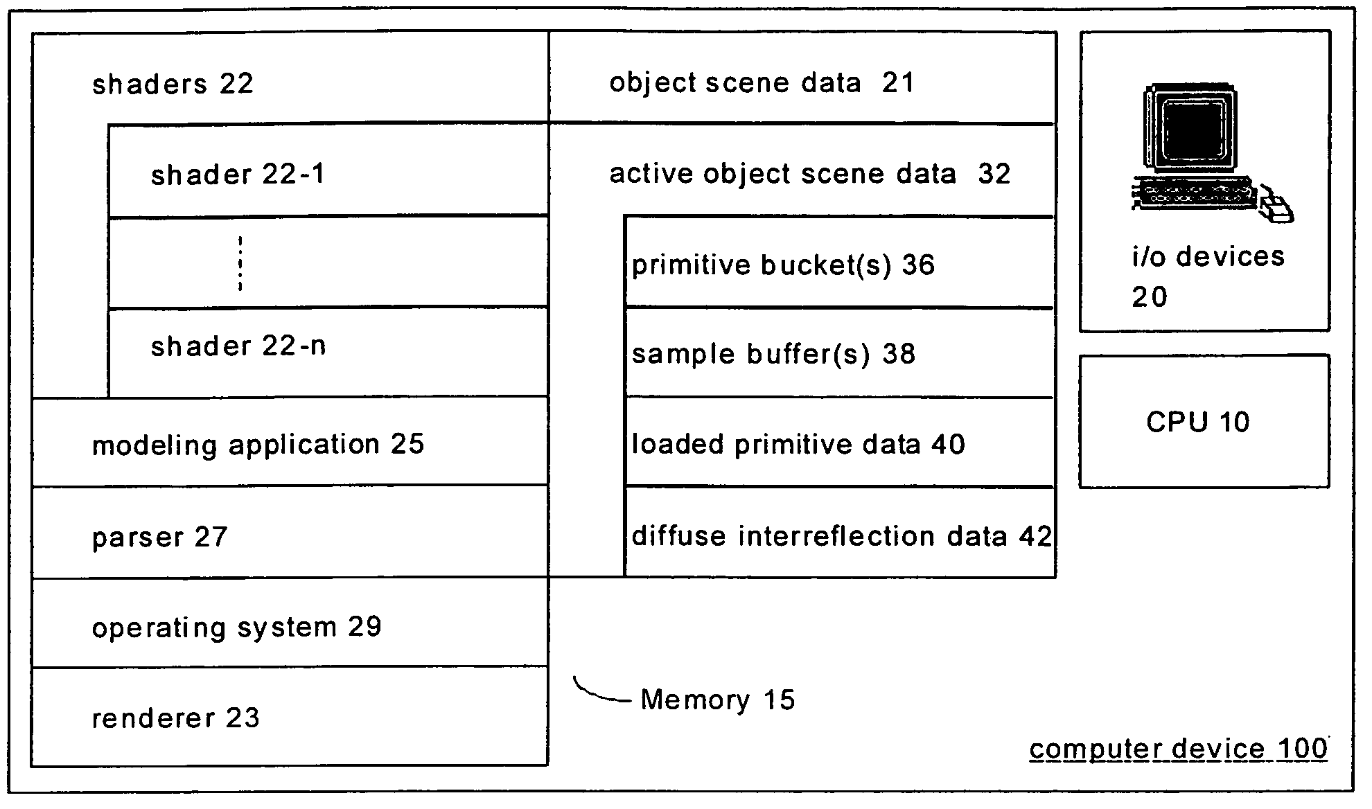
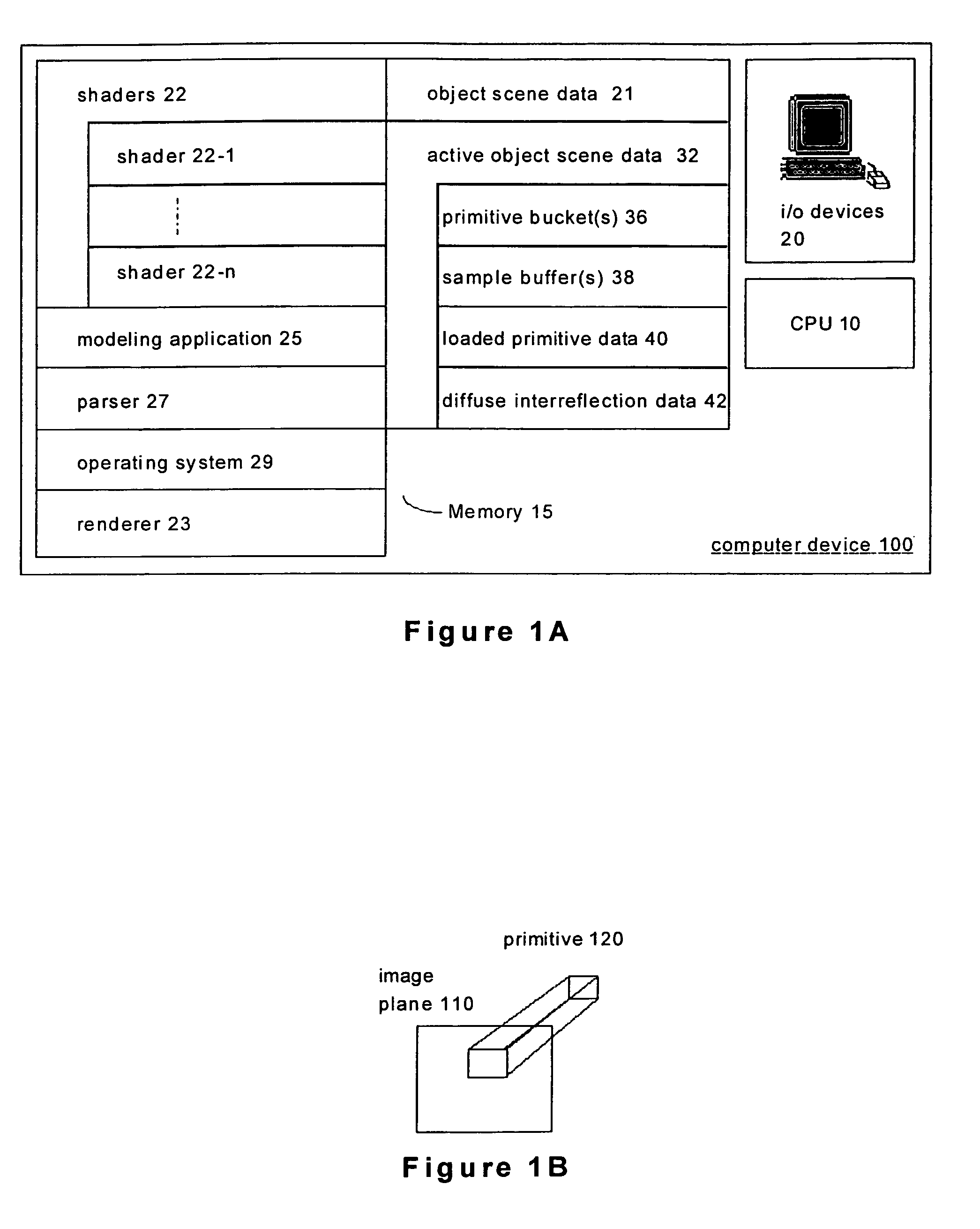
[0031]FIG. 1A shows a computer device 100 configured to execute the various embodiments of the present invention described below. Included in the computer device 100 is a central processing unit (CPU) 10, a memory 15, and i / o devices 20. The CPU 10 executes instructions as directed by the operating system 29 and other programs maintained in the memory 15 and sends control signals to various hardware components included in the computer device 100. The memory 15 typically comprises high speed random access memory as well as non-volatile storage such as disk storage. In preferred embodiments of the present invention, the memory 15 typically includes object scene data 21, shaders 22, a renderer 23, a modeling application 25, a parser 27, an operating system 29, and active object scene data 32.

[0032]Object scene data 21 is typically static information maintained in the non-volatile section of the memory 15. The object scene data 21 may be maintained in any type of data structure (e.g., d...


PUM


Abstract

The present invention is related to rendering computer animated video and / or images generally, and to improving the calculation of diffusely reflected light. The present invention includes a system and method of computing diffusely reflected light at one or more positions on surfaces in an object scene from object scene data. The present invention typically includes the step of and / or instructions for selecting a non-regular order for processing a plurality of positions on a surface—the plurality of positions having been predetermined. The present invention also includes the step of and / or instruction for processing the plurality of positions in the non-regular order. This processing typically includes computing diffusely reflected light at a position in the plurality of positions by reference to diffusely reflected light incident on the position when deriving the diffusely reflected light at the position by reference to diffusely reflected light at other positions computed by reference to diffusely reflected light incident on the other positions is inaccurate. Alternatively, deriving the diffusely reflected light at the position by reference to the diffusely reflected light at the other positions computed by reference to diffusely reflected light incident on the other positions when deriving the diffusely reflected light at the position by reference to the diffusely reflected light at the other positions is accurate.

Description

CROSS-REFERENCES TO RELATED APPLICATIONS[0001]This application is a continuation of U.S. patent application Ser. No. 10 / 186,093, entitled “SYSTEM AND METHOD OF IMPROVED CALCULATION OF DIFFUSELY REFLECTED LIGHT,” filed Jun. 26, 2002, now U.S. Pat. No. 6,853,377. The Ser. No. 10 / 186,093 application listed above is assigned to NVIDIA Corporation, the assignee of the present invention and is hereby incorporated by reference for all purposes.[0002]This application is related to, and incorporates herein by reference, a U.S. patent application bearing Ser. No. 09 / 865,990, entitled “SYSTEM AND METHOD OF LINE SAMPLING OBJECT SCENE INFORMATION,” and commonly assigned with the present invention. This application is also related to, and incorporates herein by reference, a U.S. patent application Ser. No. 10 / 157,579, filed on May 28, 2002, entitled “SYSTEM AND METHOD RELATED TO DATA STRUCTURES IN THE CONTEXT OF A COMPUTER GRAPHICS SYSTEM,” and commonly assigned with the present invention. This a...

Claims


Application Information

Patent Timeline
Patent Type & Authority Patents(United States)
IPC IPC(8): G06T15/50
CPCG06T15/55
Inventor PHARR, MATTHEW MILTON
Owner NVIDIA CORP
Learn More