Eureka AIR delivers breakthrough ideas for toughest innovation challenges, trusted by R&D personnel around the world.

Dual mode fiber-optic interferometer with circular-core fibers and birefringent modal filters and an interfering method thereof

Inactive Publication Date: 2006-04-18
NAT SCI COUNCIL
View PDF1 Cites 0 Cited by
  • Summary
  • Abstract
  • Description
  • Claims
  • Application Information

AI Technical Summary

Benefits of technology

[0008]It is a further object of the present invention to provide an interferometer which owns the advantages of low cost, easy aligning, and adjustable visibility.

Problems solved by technology

On the contrary, in the two-fiber interferometer, it needs to consider the coherent length of the light source, namely the difference of the traveling routes of the beams in two fibers should be within the coherent length, so that the limitations of the optical paths and the spectrum characteristic are increased.
Because the second-order mode group has four eigenmodes and is hard to be excited with a single second-order mode, it causes an unstable interference pattern.
In this structure, the main difficulties are that the e-core fiber is expensive, and the polarized direction of the incident light should be aligned with the major (or minor) axis of the e-core, or it will cause the propagated light to have an elliptical polarization so as to reduce the visibility of the variation of the interference pattern from the superposition of the fundamental mode and the second-order even mode.
However, because the excited energy of the two modes in the e-core fiber cannot be controlled easily, the visibility is also hard to control.

Method used


Image

  • Dual mode fiber-optic interferometer with circular-core fibers and birefringent modal filters and an interfering method thereof
  • Dual mode fiber-optic interferometer with circular-core fibers and birefringent modal filters and an interfering method thereof
  • Dual mode fiber-optic interferometer with circular-core fibers and birefringent modal filters and an interfering method thereof

Examples


Embodiment Construction

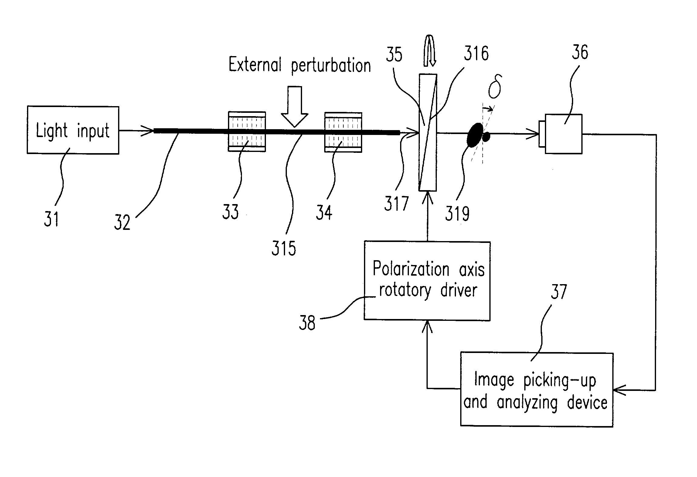
[0033]Please refer to FIG. 3(a) which illustrates the structural schematic view in a preferred embodiment according to the present invention. The structure includes a light input 31, a first dual-mode optical fiber 32, a first modal filter 33, a second dual-mode optical fiber 315, a second modal filter 34, an analyzer 35, a charge coupled device (CCD) 36, a image picking-up and analyzing device 37, and a polarization axis rotatory driver 38, wherein the analyzer 35 includes a polarization axis 316.

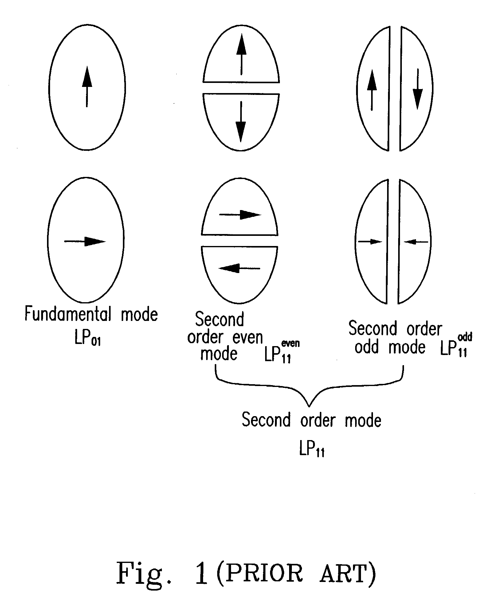
[0034]When the light input 31 is incident into the first dual-mode optical fiber 32, the HE11, TE01, TM01, and HE21 modes (all are not shown) will be excited, wherein the HE11 is a fundamental mode and the others are second-order modes. Moreover, when all these modes are propagated to the first modal filter 33, the TM01 and the HE21 will be filtered, the HE11 will be attenuated, and the TE01 will remain the same. Thus, the comparison of the attenuation ratio is TM01 and HE21>>HE11>TE01. Be...


PUM


Abstract

A fiber-optic interferometer is provided. The interferometer includes a first dual-mode optical fiber for receiving a light input and exciting a first and a second spatial, modes, a first modal processor connected to the first dual-mode optical fiber for selecting the first and the second spatial modes, a second dual-mode optical fiber connected to the first modal processor for propagating the first and the second spatial modes and producing a phase shift (Δφ) between the first and the second spatial modes in response to an external perturbation effect, a second modal processor connected to the second dual-mode optical fiber for re-selecting the first and the second spatial modes and producing a first light output interference pattern, and an analyzer connected to the second modal filter for adjusting the first light output interference pattern to produce a second light output interference pattern.

Description

FIELD OF THE INVENTION[0001]This invention relates to an interferometer and an interfering method thereof, and more particular to a fiber-optic interferometer and an interfering method thereof.BACKGROUND OF THE INVENTION[0002]Generally, the interfering-type interferometer developed in the laboratory is constructed on the Mach-Zehnder interferometer and the transmission paths thereof are substituted by the optical fibers. When there exists an external perturbation, such as the variation of temperature or pressure, it will cause a variation of a phase retardation (Δφ), namely Δφ(T) or Δφ(P), and appear a variation in an interference-intensity distribution. This is the basic mechanism for measuring the interference.[0003]When the interferometer is constructed by employing the optical fibers, there are two ways: one is using two single-mode fibers, and the other is only utilizing one dual-mode fiber. The most obvious advantages for using only one fiber are small volume, deflectable, and...

Claims


Application Information

Patent Timeline
IPC IPC(8): G01B9/02
CPCG01D5/35332G01K11/32G01D5/3538
Inventor CHEN, TIEN-JUNGCHEN, SHU-HSIA
Owner NAT SCI COUNCIL
Why Eureka
Eureka Blog
Learn More