Equipment for producing high-pressure saturated steam

a technology of high-pressure saturated steam and equipment, which is applied in the direction of steam generation using hot heat carriers, heating types, separation processes, etc., can solve the problems of large amount of energy and save time and energy

Inactive Publication Date: 2006-04-18
ZHENG YEQI
View PDF7 Cites 9 Cited by
  • Summary
  • Abstract
  • Description
  • Claims
  • Application Information

AI Technical Summary

Benefits of technology

[0003]The object of this invention is to provide a device for generating high-pressure, saturated steam with the advantages of saving time and energy, lower running cost and being able to provide higher steam temperature and pressure.THE TECHNICAL PROPOSAL OF THIS INVENTION
[0005]Compared to the state of the art, this device has the following advantages and benefits:
[0006](1) After being atomised by the atomising nozzle and heated in the heating chamber, the water from the water tank turns into steam immediately, which avoids heating up a large amount of water for steam production. This saves time and energy.
[0007](2) Whenever the device or the equipment to which steam is supplied does not require steam, the power supply can be switched off and atomisation will be stopped immediately. Thus the heating chamber will also stop the heating and steam generating process, thereby saving a large amount of energy.

Problems solved by technology

(1) After being atomised by the atomising nozzle and heated in the heating chamber, the water from the water tank turns into steam immediately, which avoids heating up a large amount of water for steam production. This saves time and energy.
(2) Whenever the device or the equipment to which steam is supplied does not require steam, the power supply can be switched off and atomisation will be stopped immediately. Thus the heating chamber will also stop the heating and steam generating process, thereby saving a large amount of energy.

Method used


Image

  • Equipment for producing high-pressure saturated steam
  • Equipment for producing high-pressure saturated steam
  • Equipment for producing high-pressure saturated steam

Examples


example 1

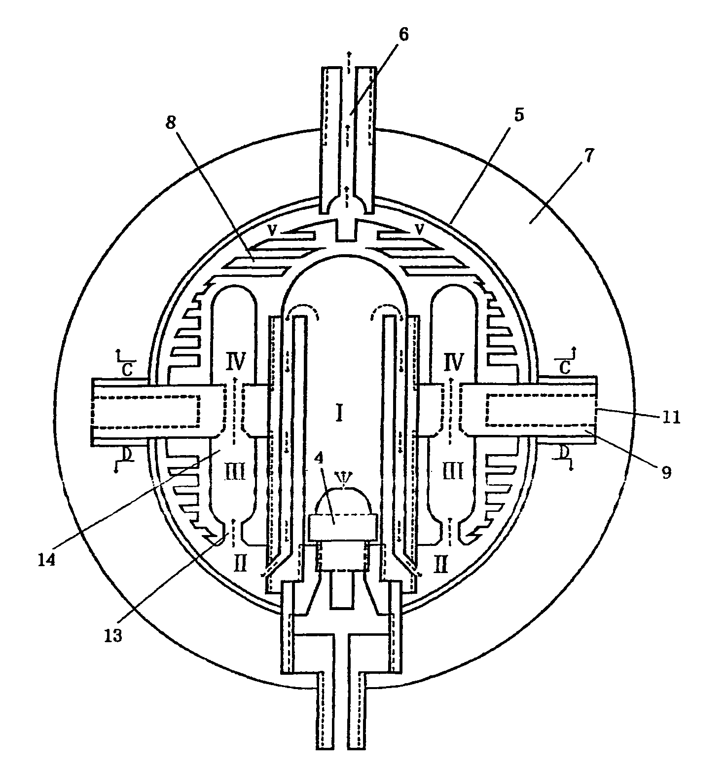
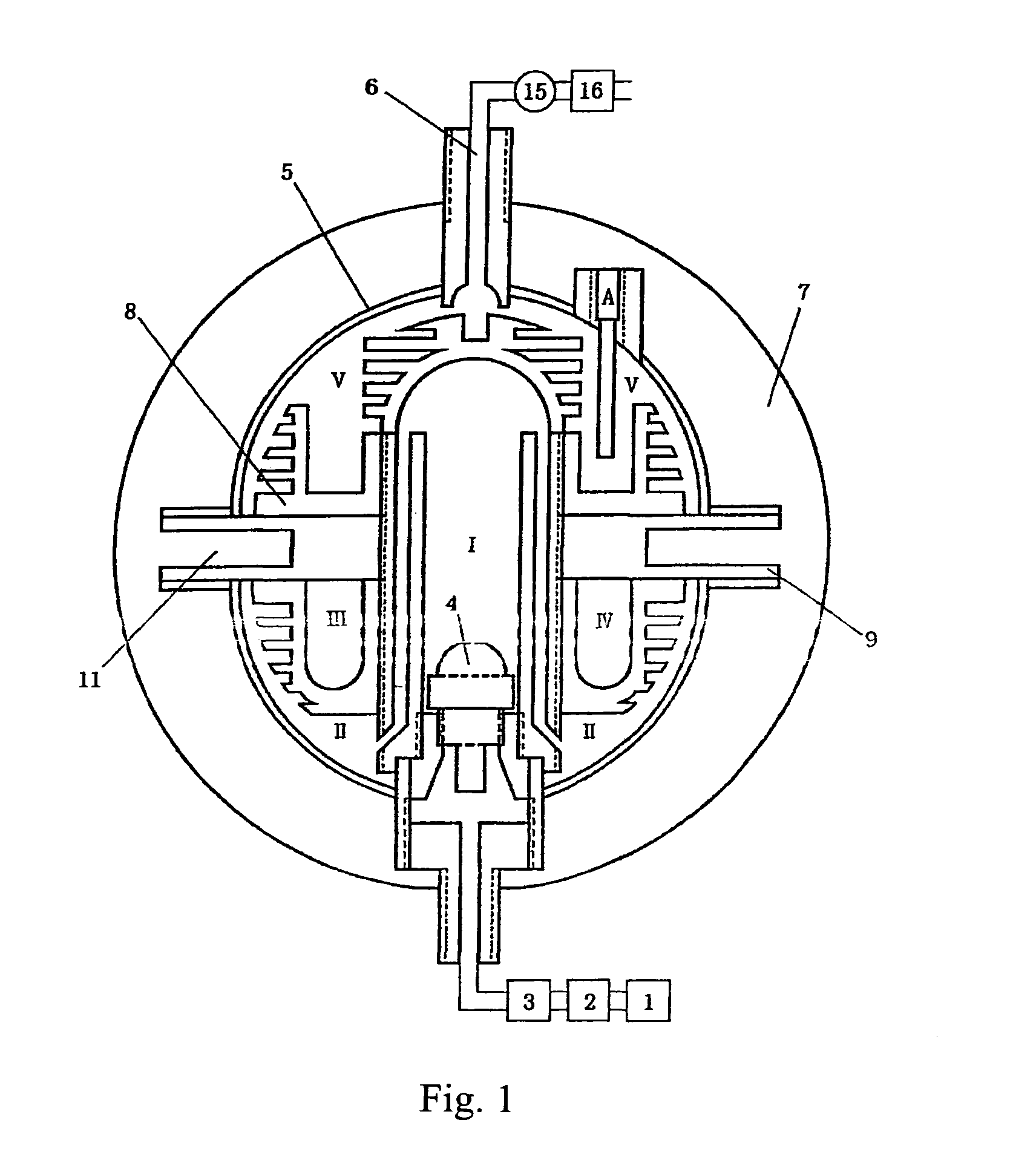
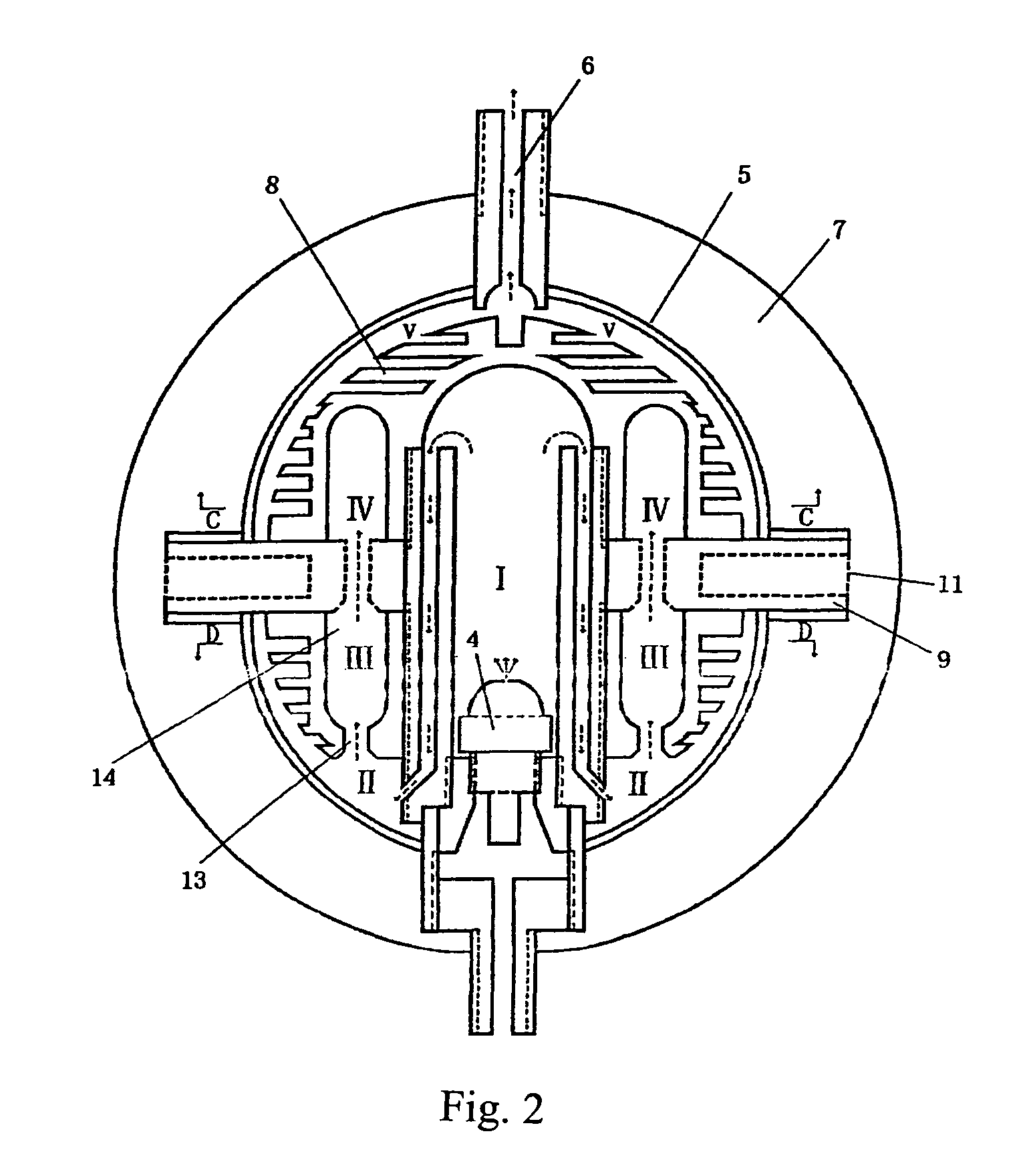
[0017]As shown in FIGS. 1, 2, 3 and 4, the said device for generating high-pressure, saturated steam is comprised of water tank 1, water pump 2, one-way valve 3, atomising nozzle 4, heating chamber 5, and steam outlet 6. They are interconnected as follows: The water pump 2 links the water tank 1 and one-way valve 3, which connects to atomising nozzle 4. Joining the atomising nozzle 4, the heat chamber 5 with a steam outlet 6, is a spherical, hollow chamber 5 covered with an external thermal insulating layer 7. Installed in the spherical, hollow chamber 5 are heating plates, which subdivide the chamber into five interconnected smaller heating cavities. The atomising nozzle 4 is connected to the first heating cavity I in the spherical, hollow chamber 5 and becomes an integral part of heating plate 8, whilst the last heating cavity V in the chamber is connected to steam outlet 6. Thermal sensors and temperature gauges are installed in the last heating chamber, i.e. the fifth heating ca...

example 2

[0020]FIG. 8 is an alternative structural diagram for subdivided heating cavities in the spherical chamber. All other details are the same as in Example 1.


PUM


Abstract

This invention relates to an equipment for producing high-pressure saturated steam. The equipment includes a water tank, a pump, a check valve, an atomizing nozzle, a heat chamber and a steam outlet. The pump is connected between water tank and the check valve. The check valve is connected with the heat chamber via the atomizing nozzle. The heat chamber having a steam outlet is hollow into which the atomizing nozzle extends. The hollow chamber is divided into many small chambers which are connected with each other successively. The equipment can produce high temperature steam rapidly and save energy.

Description

THE TECHNICAL SECTOR THIS DEVICE IS RELATED TO[0001]This invention relates to a device for generating high-pressure, saturated steam.THE PRIOR ART[0002]The application of steam is very broad, ranging from industrial, agricultural, domestic to medical applications. The traditional method to generate steam is to heat water to boiling point. Industrial boilers utilizing waste heat, domestic boilers or thermo-electric boilers may vary in their method of generating steam; the principle, however, remains the same, that is, to transmit heat via a heat conductor into water, which, through natural convection, reaches the boiling point and steam is generated. Such a method is time-consuming and uses expensive natural resources; when steam is not required, the boiling water cools off and energy is wasted. The Chinese patent 00228251.8 describes a device for generating high-pressure saturated steam. It comprises a motor, a water tank, a pressure gauge, a steam outlet, a steam chamber, a pressur...

Claims


Application Information

Patent Timeline
Patent Type & Authority Patents(United States)
IPC IPC(8): A61H33/06F22B27/16F22B1/02
CPCF22B27/16F22B1/28
Inventor ZHENG, YEQI
Owner ZHENG YEQI
Why Eureka
Try Eureka