Crop thinning apparatus and method

a technology for thinning crops and equipment, applied in the direction of thinning machines, agriculture tools and machines, adjusting devices, etc., can solve the problems of increasing the cost of crop production, increasing the cost of hand thinning, and making it difficult for farmers to compete with foreign growers with low labor costs

Inactive Publication Date: 2006-04-25
ARROWHEAD CENT +1
View PDF24 Cites 43 Cited by
  • Summary
  • Abstract
  • Description
  • Claims
  • Application Information

AI Technical Summary

Benefits of technology

[0020]The present invention relates to a crop thinning system for cutting plants in at least one crop row. The preferred system of the invention comprises a blade, an arm communicable with the blade, a cylinder communicable with the arm, a sensor for detecting plants in the crop row and producing sensor readings, and an electrica

Problems solved by technology

The cost of hand thinning is steadily increasing due to the declining availability of laborers and also due to increases in government labor regulation on migrant workers.
The high cost of hand thinning increases the cost of crop production, making it harder for farmers to compete with foreign growers who have low labor costs.
The cost of hand labor has gone up considerably in the last five years.
Crop thinners currently available do not provide the ability to distinguish a weed from a plant which was intentionally planted.
They also cannot distinguish between a healthy plant and a diseased or dead plant.
Further, each of these devices relies on a sharp blade which is forced beneath the soil line where it remains while it is drug through the dirt, thus severing the roots of unwanted plants.
Further, none of these devices selectively removes dead or dying crop plants, or selectively removes weeds.
While the device is large and bulk

Method used


Image

  • Crop thinning apparatus and method
  • Crop thinning apparatus and method
  • Crop thinning apparatus and method

Examples


example 1

Clipped Chile Re-growth Test

[0066]A test was conducted at a research farm where three plots of different varieties of red chile peppers were clipped at different sections. The three different variety plots were labeled as B-58, B-18 and Sonora. Each of the three varieties were cut by hand to determine where the invention should cut the plants at three different times (repetitions 1, 2, and 3 with each repetition consisting of 10 chile plants). Repetition 1 was performed when the chile plants were cut below the cotyledons. (The cotyledons are the first seed leaves that break out of the soil. The next leaves to appear after these are the first true leaves, followed by the second true leaves.) Repetition 2 was performed wherein the chiles were cut below the first true leaves. Repetition 3 was performed wherein the chilies which were cut below their second true leaves. FIG. 7 shows the results of this experiment. As shown in FIG. 7, the least amount of re-growth occurred in repetition 1...

example 2

[0067]A John Deere mechanical sugar beet thinner was modified as an intermediate step in developing a prototype crop thinner that would cut chile stems below the cotyledons. The Solid Works™ program was used to modify machine specifications so that it could adjust to rapid changes in plant height during early season growth. The program allowed one to accurately determine dimensions for new blade arms, blades, and sensor. Parts were cut from metal using the PlasmaCam™, a machine that works from Solid Works™ specifications. The sensor was a momentary switch which had a stainless steel plate connected to it. The plate on the new sensor was made larger than the sensor on the beet thinner to ensure that chile plants could make contact with it. The PlasmaCam™ cut the parts out of sheet metal.

[0068]In a first test, a modified John Deere thinner was used. The chile plants were about three to four inches tall. Two mechanical thinner units were attached to the tool bar. Before thinning, there...

example 3

[0071]Based on the results of the four tests using the John Deere thinner, appropriate modifications were made in order to attempt to optimize the machine. With those modifications, there still existed some problems that played a major role in how well the thinner cut the chile plants as they grew taller. The John Deere thinner did not easily stay in line with the field rows, thus necessitating constant realignment so that the sensor could operate and actuate the blade arm properly.

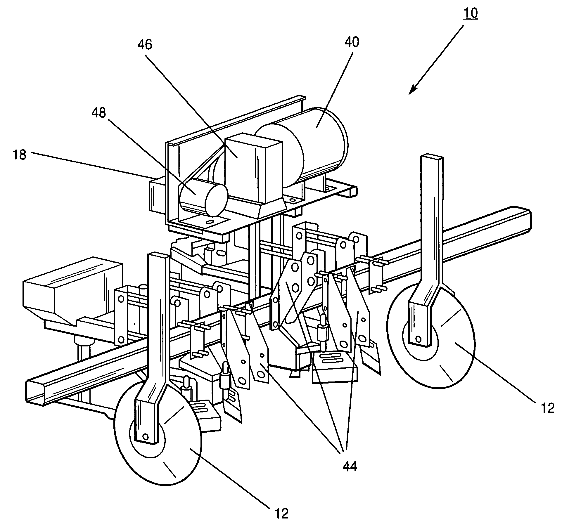
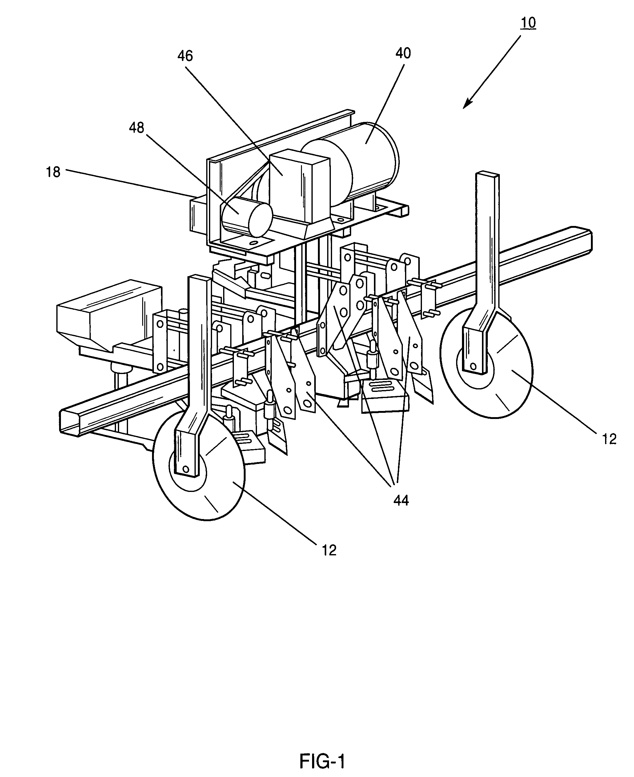
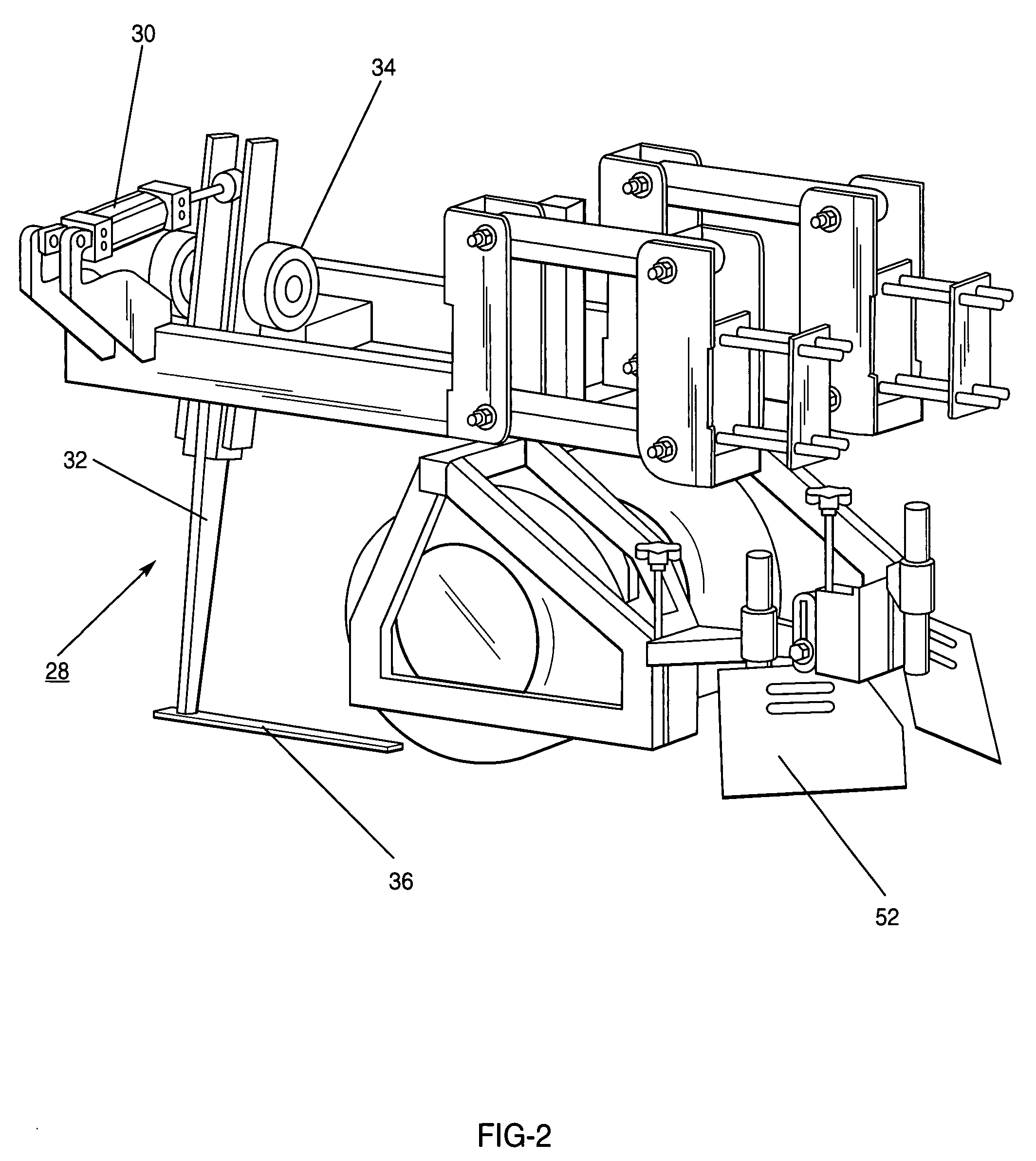
[0072]The Solid Works™ computer program was used to develop the crop thinner apparatus of the present invention. The apparatus includes features similar to the John Deere, but with substantive modifications that improve cost effectiveness and make the apparatus simpler to operate and adjust. Electric actuators, rather than hydraulic solenoids, were to actuate the blade. The wheels were eliminated and screw jacks added to allow a wide range of height adjustment.

[0073]The plate of the sensor was converted t...


PUM


Abstract

A method and apparatus for mechanically thinning crops, particularly those planted in rows. One or more crop thinning units are connected to the back of a tractor or other vehicle. Each of the units has the ability to sense plants and activate an arm which has a blade disposed thereon. An electronic control system enables data from several sensors to be evaluated such that plants may be selectively removed based on pre-established criteria. Sensors differentiate between weeds and plants, and maintain the cutting units above the crop rows.

Description

CROSS-REFERENCE TO RELATED APPLICATIONS[0001]This application claims priority to and the benefit of U.S. Provisional Patent Application Ser. No. 60 / 466,544, entitled “Crop Thinning Apparatus and Method,” to Hernandez et al., filed on Apr. 29, 2003, and U.S. Provisional Patent Application Ser. No. 60 / 484,452, entitled “Crop Thinning Apparatus and Method,” to Eaton et al., filed on Jul. 1, 2003, and the specifications and drawings thereof are incorporated herein by reference.BACKGROUND OF THE INVENTION[0002]1. Field of the Invention (Technical Field)[0003]The present invention relates to a method and apparatus for thinning crops. More particularly, the present invention relates to a method and apparatus for selectively thinning row type crops.[0004]2. Description of Related Art[0005]Note that the following discussion refers to a number of publications by author(s) and year of publication, and that due to recent publication dates certain publications are not to be considered as prior a...

Claims


Application Information

Patent Timeline
IPC IPC(8): A01G3/04
CPCA01B41/06
Inventor EATON, WESLEYHERBON, RYANHERNANDEZ, VINCE
Owner ARROWHEAD CENT
Why Eureka
Try Eureka