Structure of heat conductive plate

a technology of heat conductive plate and structure, which is applied in the direction of insulated conductors, cables, semiconductor/solid-state device details, etc., can solve the problems that conventional aluminum extruded heat sinks and cooling fans cannot meet the requirements, and achieve the effect of improving heat transferring efficiency

Inactive Publication Date: 2006-04-25
PYROSWIFT HOLDING CO LIMITED
View PDF19 Cites 45 Cited by
  • Summary
  • Abstract
  • Description
  • Claims
  • Application Information

AI Technical Summary

Benefits of technology

[0008]The present invention is to provide a structure of a heat conductive plate of which a wick structure to be formed on a supporting member is firmly mounted to the inner wall of the heat conductive plate so as to improve the heat transferring efficiency.
[0009]Further, the present invention is to provide a structure of a heat conductive plate with increasing cooling area inside to make the heated working fluid from the heat source capable of being rapidly condensed to liquid.
[0010]Still further, the present invention is to provide a structure of a heat conductive plate with enhanced capillary absorption ability to rapidly circulate working fluid for operation, thereby the variation and speed of the vaporization of the working fluid are increased to promote the dissipating efficiency of the heat conductive plate.

Problems solved by technology

However, when the higher heat is produced due to the faster arithmetic of the CPU, a conventional aluminum extruded heat sink and cooling fan cannot meet the requirement.

Method used


Image

  • Structure of heat conductive plate
  • Structure of heat conductive plate
  • Structure of heat conductive plate

Examples


Embodiment Construction

[0023]Reference will now be made in detail to the preferred embodiments of the present invention, examples of which are illustrated in the accompanying drawings. Wherever possible, the same reference numbers are used in the drawings and the description to refer to the same or like parts.

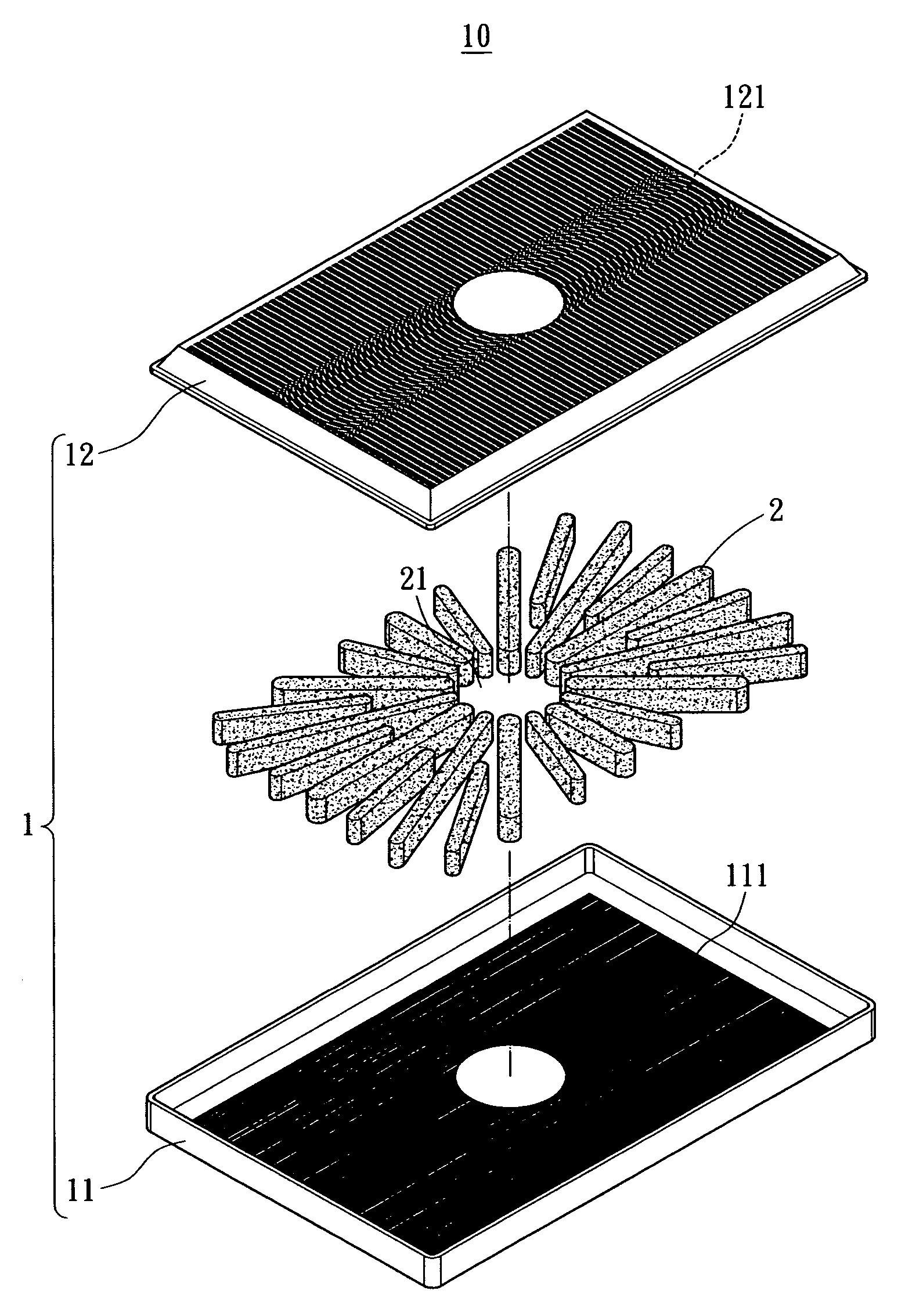
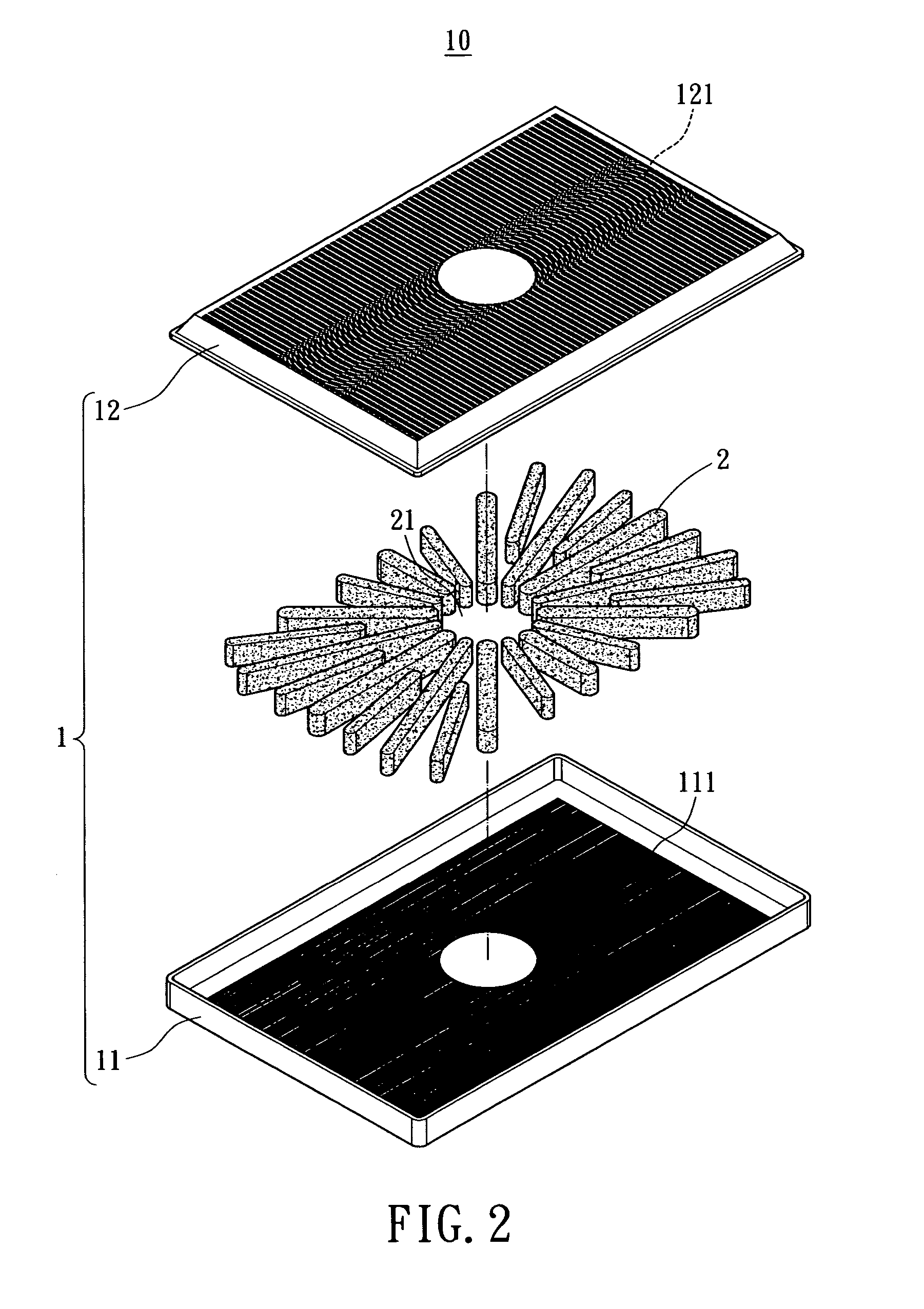
[0024]Referring to FIGS. 2 and 3, a heat conductive plate 10 utilized for a CPU 20 (as shown in FIG. 7) to proceed the operation of the heat transfer includes a hollow case 1 having a bottom cover 11 and a top cover 12. A plurality of lateral grooves 111 and 121 are respectively formed on an inner surface of the bottom and top covers 11 and 12. Location relative to the CPU 20 should have a small mount of metal sinters formed on the bottom and top covers 11 and 12.

[0025]A plurality of supports 2 is located inside the heat plate 10, and each support 2 is coordinated to the size of the case 1 and uniformly distributed. In the embodiments of the present invention, the supports 2 are radially arranged, an...


PUM


Abstract

A heat conductive plate includes a hollow case and a plurality of grooves respectively formed on the inner top wall and the inner bottom wall of the case. In addition, a plurality of supporting members are positioned in the case by way of powder sintering, wherein each surface of the supporting members has a porous wick structure formed thereon. Thus, the case can be sustained by the supports with each wick structure firmly mounted in the grooves of the inner walls thereof. When performing heat transferring, the working fluid is heated to be formed as vapor by the electronic element mounted on the outer bottom surface so as to flow toward the inner top surface of the case. The working fluid is then cooled to be liquid again to be absorbed by the wick structures of the supporting members and be transported toward the inner bottom of the case.

Description

BACKGROUND OF THE INVENTION[0001]The present invention relates to a structure of a heat conductive plate, more particular, to a structure of a heat conductive plate for heat interchange with an electric element (such as CPU), which can increase the variation and speed of the vaporation of working fluid to promote the cooling efficiency.[0002]With developing of the technology and industry, the arithmetic of computer becomes faster and faster, especially when the faster operation of the computer is, the higher heat is produced. In order to effectively dissipate the highly concentrated heat out of the host and maintain the CPU under an allowable temperature, a heat sink is positioned in the CPU to assist the cooling and expedite the dissipation. However, when the higher heat is produced due to the faster arithmetic of the CPU, a conventional aluminum extruded heat sink and cooling fan cannot meet the requirement.[0003]Therefore, a conventional heat conductive plate is provided. As show...

Claims


Application Information

Patent Timeline
Patent Type & Authority Patents(United States)
IPC IPC(8): F28D15/00
CPCF28D15/0233F28D15/046H01L23/427H01L2924/0002H01L2924/00
Inventor WANG, CHIN WENWANG, PEI CHOAWANG, CHING CHUNG
Owner PYROSWIFT HOLDING CO LIMITED
Why Eureka
Try Eureka