Fuel injection valve

a technology of fuel injection valve and fuel injection pump, which is applied in the direction of fuel injecting pump, machine/engine, generator/motor, etc., and can solve problems such as cost savings

Inactive Publication Date: 2006-04-25
ROBERT BOSCH GMBH
View PDF10 Cites 14 Cited by
  • Summary
  • Abstract
  • Description
  • Claims
  • Application Information

AI Technical Summary

Benefits of technology

[0007]The fuel injector of the present invention has the advantage over the related art that the thermal expansion is able to be adjusted more precisely by the prestressing of the spring sleeve. Due to the prestressing, the thermal expansion may be influenced to a slight degree and adjusted more precisely to the thermal expansion of the actuator. Moreover, it is advantageous that the compensation section is not subjected to a tensile load and may thus have a less complicated design. Therefore, the material requirement with respect to materials having no, or only negative, thermal expansion is reduced, resulting in considerable cost savings since these materials are quite expensive. The compensation section is retained solely by the clamping between the upper valve-body section and lower valve-body section and requires no unit volume and no machining for connections, such as threaded bores.
[0009]Advantageously, the tube spring is screw-fitted to the lower valve-body section and surrounds the upper valve-body section at a flange. Owing to the thread, the prestress is able to be adjusted very precisely and in a simple manner, especially when using a fine thread.
[0010]The tube spring may be made of Invar. When the tube spring is made of Invar, i.e., a nickel / iron alloy, a reduction in the initial stress in response to a temperature increase is avoided.
[0012]The compensation section may have the form of a cylinder with surface-ground end faces. In this way, the compensation section is able to be manufactured in an inexpensive manner from a semi-finished product. The sealing may be achieved by surface-ground areas, which require no additional formations for sealing means, such as an o-ring.

Problems solved by technology

Therefore, the material requirement with respect to materials having no, or only negative, thermal expansion is reduced, resulting in considerable cost savings since these materials are quite expensive.

Method used


Image

  • Fuel injection valve
  • Fuel injection valve

Examples


Embodiment Construction

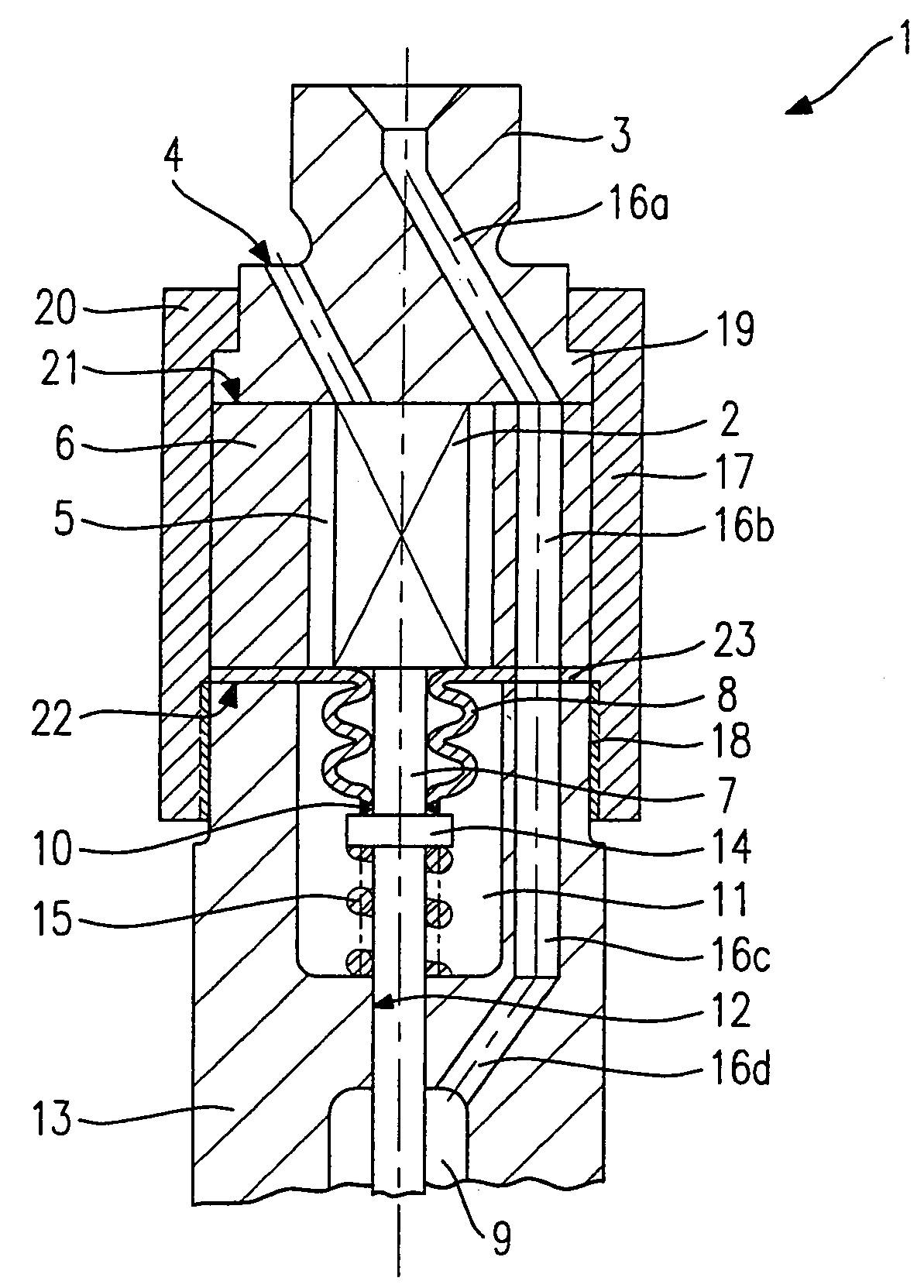
[0015]FIG. 1 shows a schematic section through an exemplary embodiment of a fuel injector 1 configured according to the present invention. An actuator 2 is braced against an upper valve-body section 3 and is controlled via a connecting bore 4 in upper valve-body section 3 by way of connecting lines (not shown here). Actuator 2 is located in an actuator chamber 5, which, radially toward the outside, is bounded by a compensation sleeve 6. Actuator 2 transmits a lifting movement to a valve needle 9 via an actuator tappet 7. Affixed on actuator 7, via a welded seam 10, is a corrugated tube 8, which seals actuator chamber 5 from a fuel chamber 11. Valve needle 9 is joined to a valve-closure member (not shown here), which cooperates with a valve-seat surface to form a valve-sealing seat. A guide bore 12 in a lower valve-body section 13 guides valve needle 9.

[0016]At its end facing actuator tappet 7, valve needle 9 has a flange 14 against which a valve spring 15 abuts, valve spring 15 bein...


PUM


Abstract

In a fuel injector, in particular a fuel injector for fuel-injection systems of internal combustion engines, a piezoelectric or magnetostrictive actuator is surrounded by a compensation sleeve. The compensation sleeve is made of a material exhibiting virtually no, or negative, thermal expansion, so that the thermal expansion of the compensation sleeve and that of an upper valve-body section and / or lower valve-body section essentially corresponds to the thermal expansion of the actuator and effective transmission elements to the valve-sealing seat. The compensation sleeve, radially on the outside, is enclosed by a spring sleeve, which connects the lower valve-body section to the upper valve-body section and prestresses the compensation sleeve for pressure.

Description

BACKGROUND INFORMATION[0001]From German Patent Application No. DE 195 38 791, a fuel injector for fuel-injection systems of internal combustion engines is known which has a piezoelectric device guided in a valve member whose piezoactuator, which cooperates with a needle-type valve-closure member, is fixedly clamped in an end piece facing away from the closure member and, upon activation, lifts the valve-closure member off from a valve seat. The end piece is fixedly connected to the valve member tightly surrounding the piezoactuator. The valve member is made of a material that compensates for the temperature-related longitudinal changes of the piezoactuator at least approximately.[0002]In one embodiment, a fuel injector is known from German Patent Application No. DE 195 38 791 whose valve body is embodied as a two-part sleeve, which has sleeve parts that are arranged coaxially with respect to one another. These sleeve parts are situated in such a way that they follow each other in an...

Claims


Application Information

Patent Timeline
Patent Type & Authority Patents(United States)
IPC IPC(8): F02M47/02F02M51/06F02M59/46F02M61/08F02M61/16H01L41/09H01L41/12H02N2/00
CPCF02M51/0603F02M61/08F02M63/0026F02M61/167F02M2200/26
Inventor BOCKING, FRIEDRICH
Owner ROBERT BOSCH GMBH
Why Eureka
Try Eureka