
Fuel injection valve

a technology of fuel injection valve and injector, which is applied in the direction of fuel injection apparatus, spraying apparatus, feeding system, etc., can solve the problems of undesired burrs at the outlet of the swirl channel, additional expense in removing the residue after the swirl channel has been produced, and difficulty or impossible to produce tiny droplets of liquefied material produced in the drilling process, etc. cost

Inactive Publication Date: 2006-04-25
ROBERT BOSCH GMBH
View PDF10 Cites 52 Cited by
  • Summary
  • Abstract
  • Description
  • Claims
  • Application Information

AI Technical Summary

Benefits of technology

The present invention provides a fuel injector with advantages of cost-effective production methods. The swirl channels in the injector are designed in a way that allows for laser drilling without the need for a protective form, which could leave residue and cause burrs. The swirl channels can also be produced in a cost-effective manner in one clamping, and tiny droplets of produced liquid material can be blown off or suctioned off during the drilling procedure. The dimensions of the central bore are too small to accommodate a laser nozzle, so the swirl channels are introduced so far up at the upstream end of the valve-seat member that the laser nozzle does not contact the forms of the valve-seat member that lie downstream. The swirl channels have a smooth cross-section transition to minimize the swirl-chamber volume and allow for a smooth rotation of the enclosed fluid mass at the beginning of the spray-discharge. The cross-section forms of the swirl channels can have any desired shape, such as circular, elliptical, square, rectangular, triangular, polygonal, or trapezoid.

Problems solved by technology

Since such a protective form would leave residue behind on the surfaces of the valve-seat member as a result of the laser bombardment, and the protective form would block the bore end of the swirl-channel bore, it would also be more difficult or impossible for tiny droplets from liquefied material produced in the drilling process to be blown off or suctioned off from the swirl-channel bore during the drilling procedure.
Removing this residue after the swirl channel has been produced would involve additional expense.
A retroactive internal grinding would cause the formation of undesired burrs at the swirl-channel outlet.
Since the dimensions of the central bore are too small in fuel injectors to accommodate a laser nozzle, it is practically impossible to drill counter to the swirl-channel flow direction.

Method used


Image

  • Fuel injection valve
  • Fuel injection valve
  • Fuel injection valve

Examples


Embodiment Construction

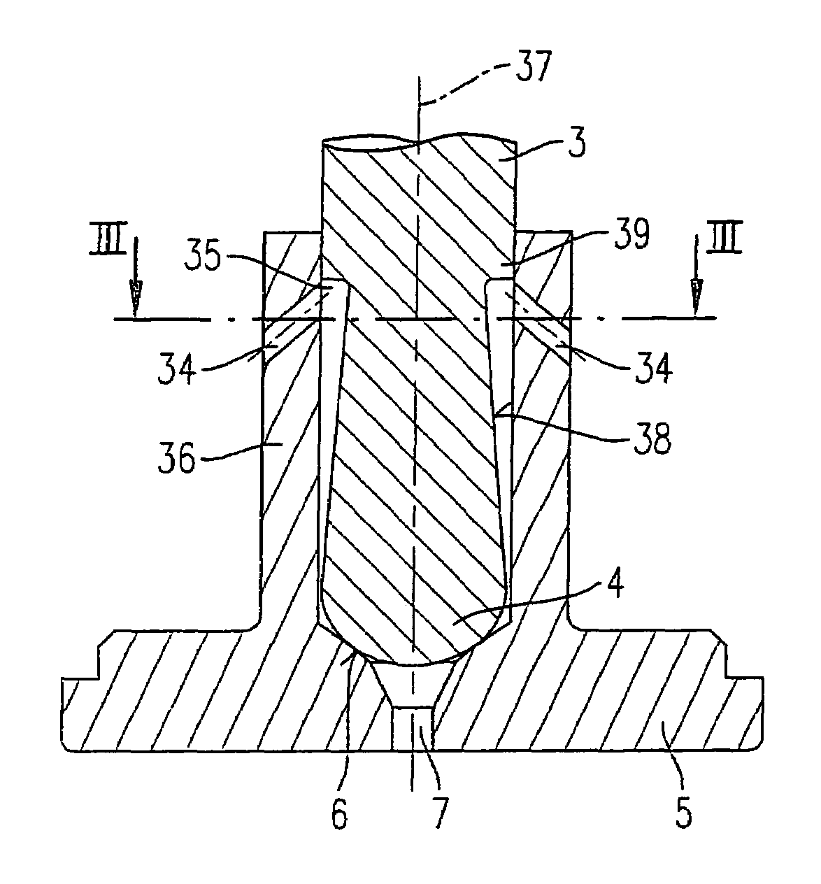
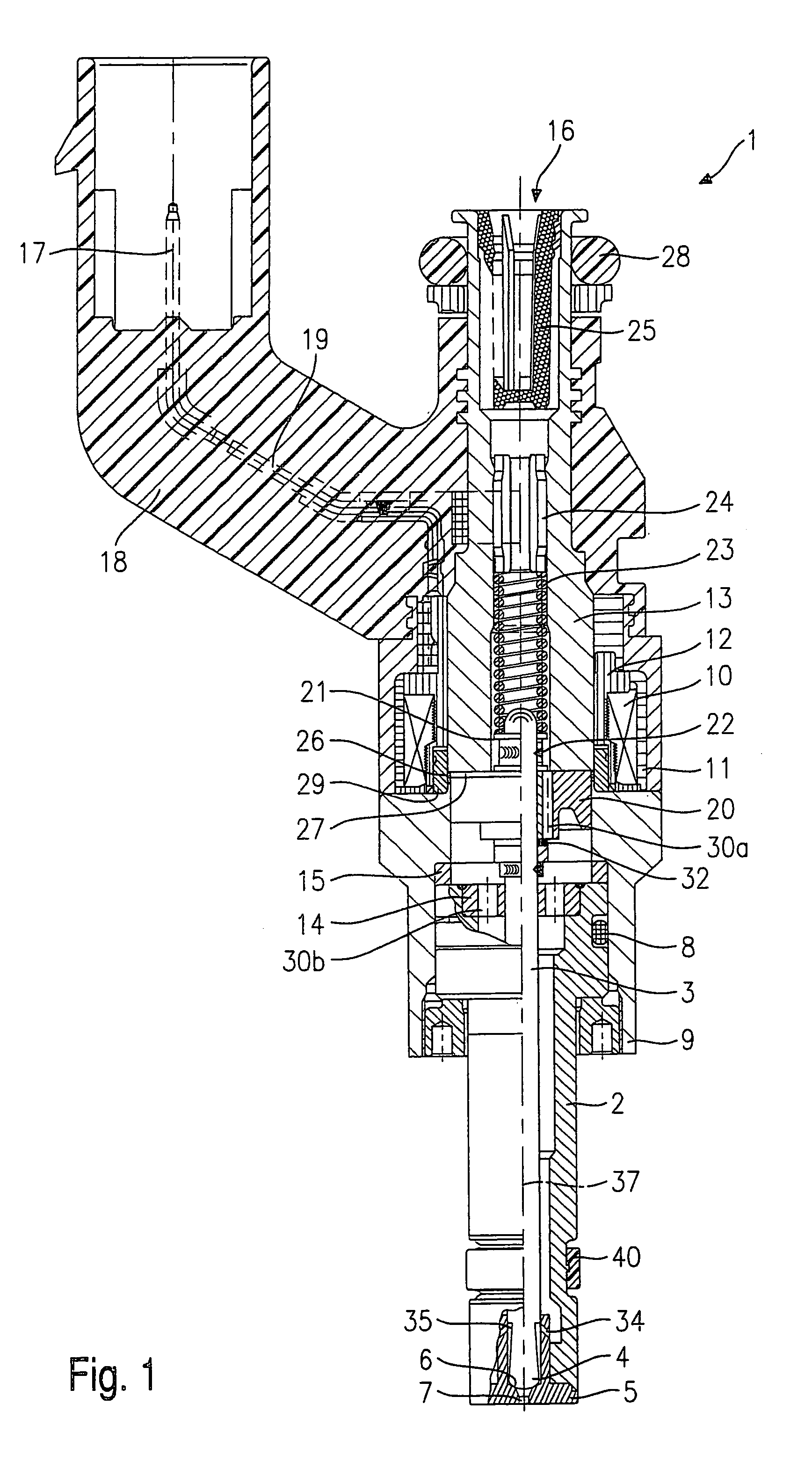
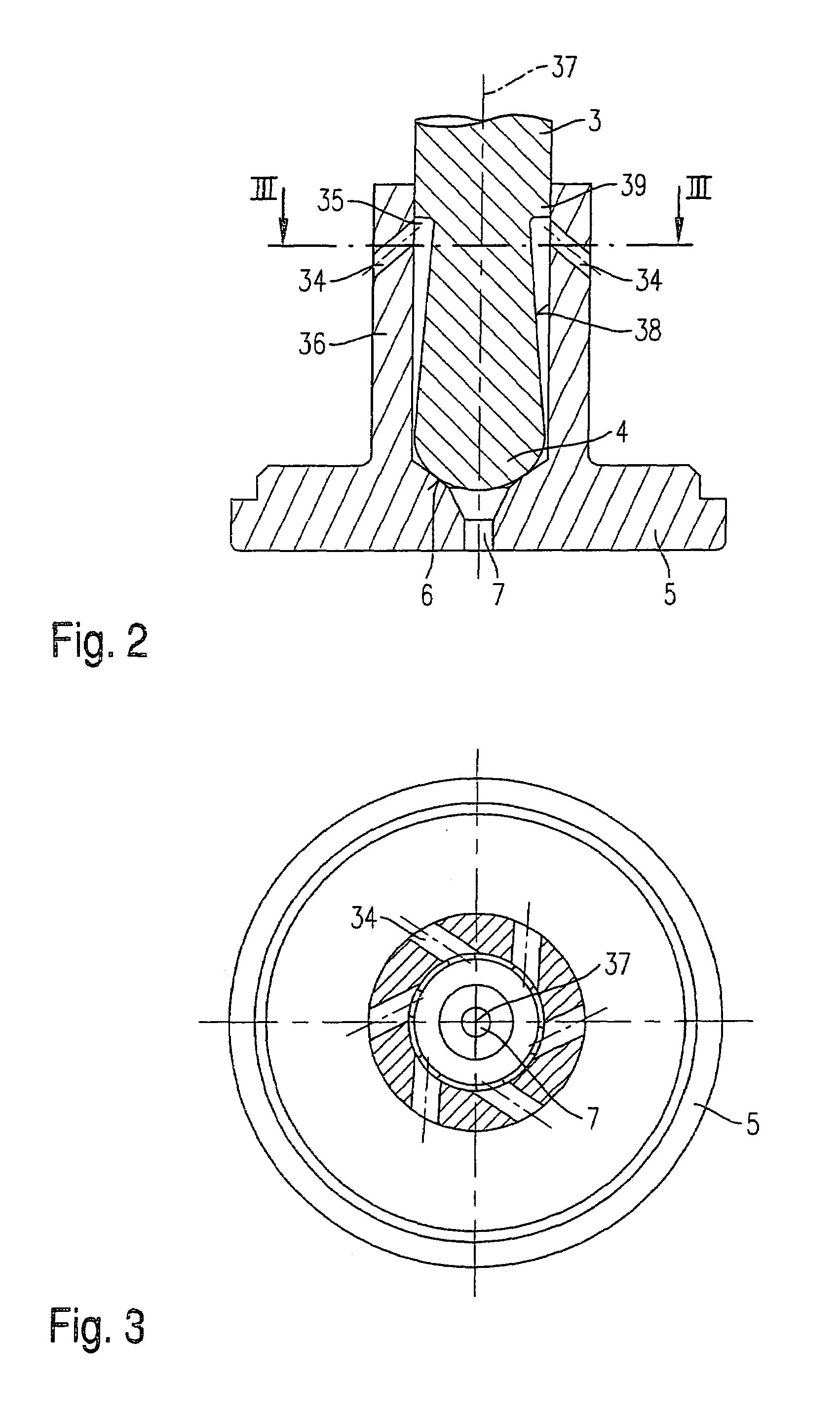
[0016]The first exemplary embodiment of a fuel injector 1 according to the present invention, shown in FIG. 1, is configured for fuel-injection systems of mixture-compressing internal combustion engines having externally supplied ignition. Fuel injector 1 is suited, for example, for the direct injection of fuel into a combustion chamber (not shown) of an internal combustion engine.

[0017]Fuel injector 1 is made up of a nozzle body 2 in which a valve needle 3 is positioned. Valve needle 3 is in operative connection with a valve-closure member 4, which cooperates with a valve-seat surface 6 positioned on a valve-seat member 5 to form a sealing seat. Fuel injector 1 in the exemplary embodiment is an inwardly opening fuel injector. Nozzle body 2 is sealed from outer pole 9 of a magnetic coil 10 by a seal 8. Magnetic coil 10 is encapsulated in a coil housing 11 and wound on a coil brace 12, which rests against an inner pole 13 of magnetic coil 10. Inner pole 13 and outer pole 9 are separa...


PUM


Abstract

A fuel injector for the direct injection of fuel into a combustion chamber of an internal combustion engine is provided, which injector includes a valve needle having at its spray-discharge end a valve-closure member, which cooperates with a valve-seat surface formed on a valve-seat member to form a sealing seat. At least one swirl channel is provided in a section of the valve-seat member surrounding the valve needle, and at least one spray-discharge orifice is provided in the valve-seat member. The at least one swirl channel, when viewed through the swirl channel in the flow direction of the fuel, is inclined counter to the spray-discharge direction relative to the center axis of the valve needle.

Description

FIELD OF THE INVENTION[0001]The present invention is directed to a fuel injector for an internal combustion engine.BACKGROUND INFORMATION[0002]Published German patent document DE 196 25 059 discloses a fuel injector having swirl channels (referred to as fuel channels there), which, in their position relative to the axis of the valve needle, are inclined in the direction of the main flow of the fuel. In published German patent document DE 196 25 059, the incline of the swirl channels is used for the injection of a fuel jet directly into the combustion chamber following in the discharge direction, through the swirl chamber disposed downstream from the valve-seat surface in the main-flow direction, and through the spray-discharge orifice. In this context, “directly” means without the jet striking parts of the fuel injector lying downstream from the spray-discharge orifice of the swirl chamber. The objective in this case is to influence the direction, form and the skeining of the emergi...

Claims


Application Information

Patent Timeline
Patent Type & Authority Patents(United States)
IPC IPC(8): F02M61/16F02M61/18F02M51/02F02M51/06F02M61/10F02M61/12F02M63/00
CPCF02M51/0685F02M61/162F02M61/12F02M2200/306F02M61/16
Inventor DANTES, GUENTERHEYSE, JOERG
Owner ROBERT BOSCH GMBH
Learn More