
Rotating instrumented suspension stop for measuring vertical forces

a technology of suspension stop and rotating instrument, which is applied in the direction of shock absorber, instrument, force/torque/work measurement apparatus, etc., can solve the problems of difficult exact determination of vertical force, certain limitations of measurement strategies,

Inactive Publication Date: 2006-04-25
SNR ROULEMENTS SA
View PDF6 Cites 41 Cited by
  • Summary
  • Abstract
  • Description
  • Claims
  • Application Information

AI Technical Summary

Benefits of technology

[0011]To this end, and according to a first aspect, the invention proposes a suspension stop for a motor vehicle wheel of the type comprising a fixed member intended to be fixed to the chassis of the vehicle and a rotating member intended to be fixed to the suspension spring so as to be rotationally moved under the effect of the forces exerted by the said spring, the said stop comprising a device for measuring

Problems solved by technology

However, these measurement strategies have a certain number of limitations.
In particular, when the measurement is made on the tyre, which is a rotating component, there are posed problems of transmitting the signal in a fixed reference frame so as to be able to derive the modulus of forces therefrom, and this all the more critically since the signals are numerous and must be analysed in real time in order to be able to control the assistance systems.
Concerning the measurement on the wheel-set components, the main problem which is posed is that of the analysis of the signals in order to derive therefrom the modulus of forces respectively in the three directions in space.
The effect of the transverse force will therefore be preponderant on the effect of the vertical force, which makes the exact determination of this vertical force difficult.

Method used


Image

  • Rotating instrumented suspension stop for measuring vertical forces
  • Rotating instrumented suspension stop for measuring vertical forces
  • Rotating instrumented suspension stop for measuring vertical forces

Examples


Embodiment Construction

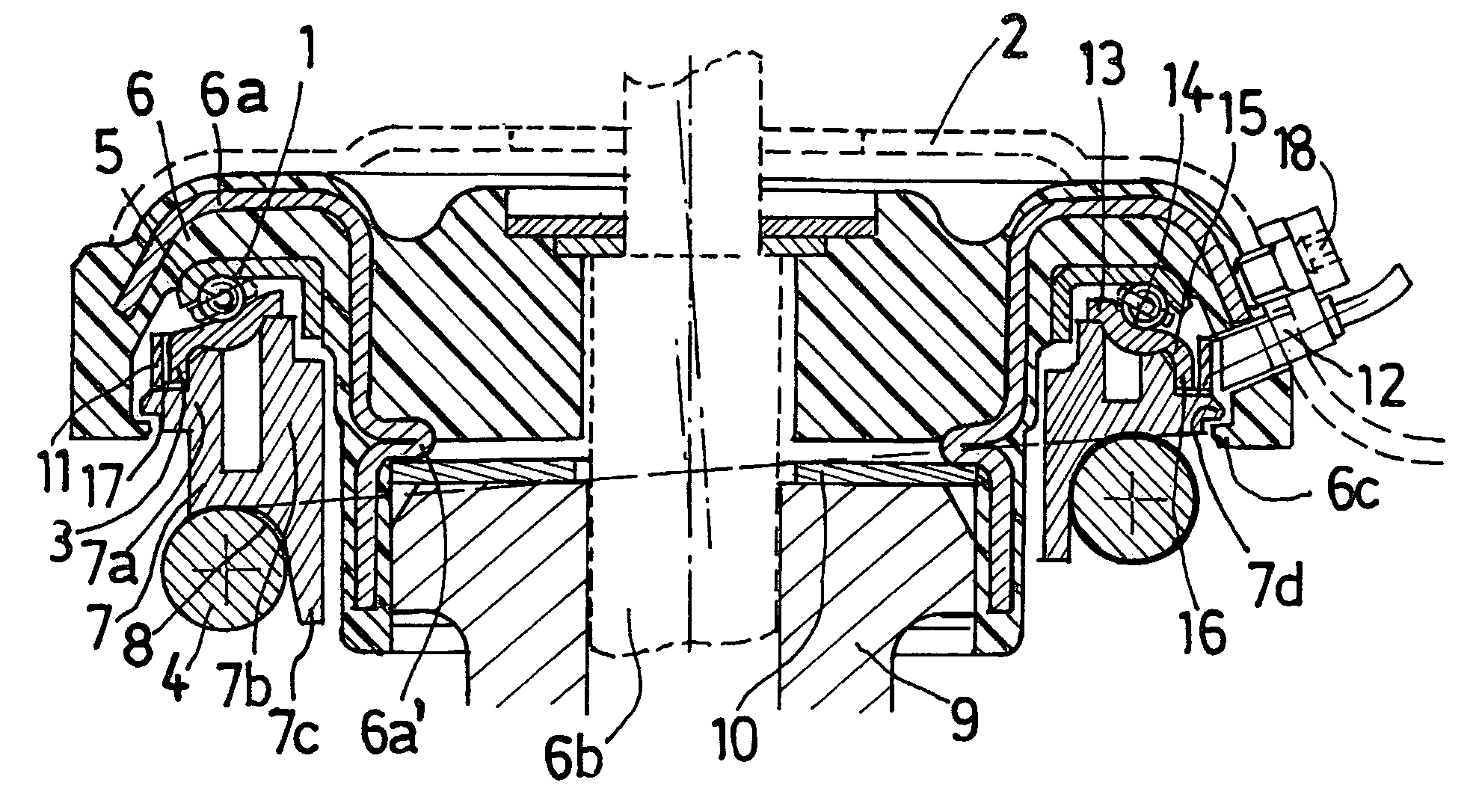
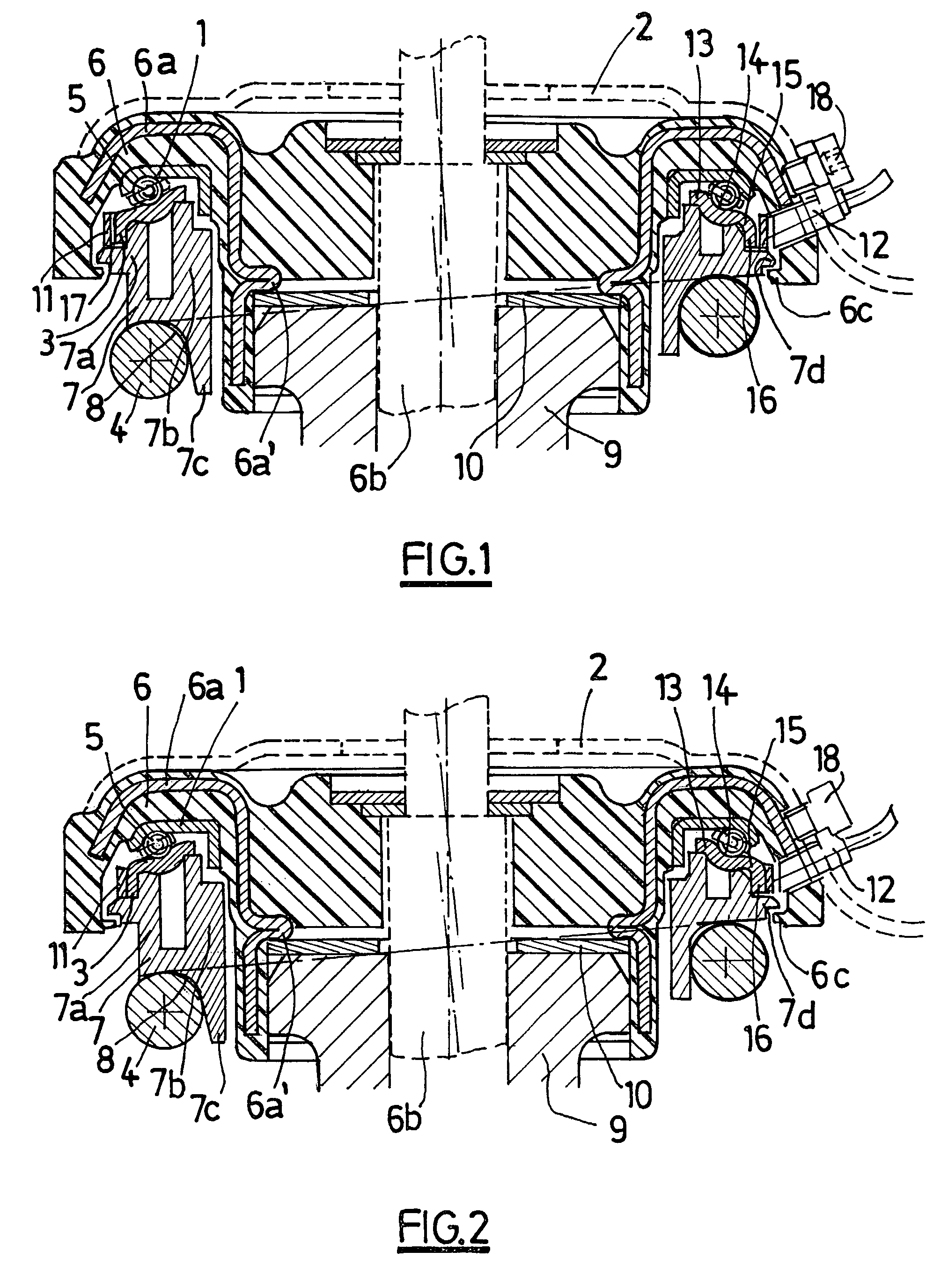
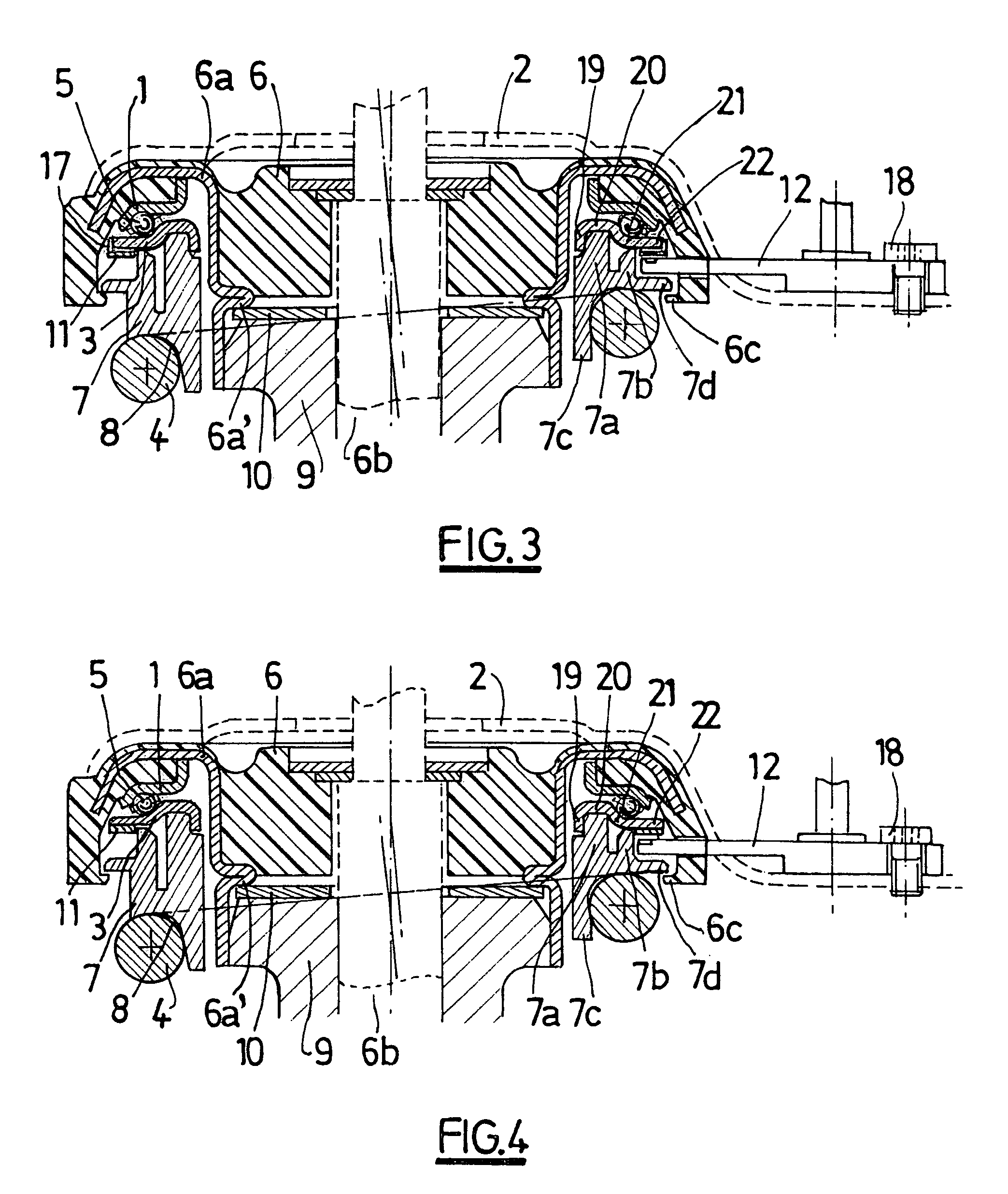
[0020]In relation to the figures, a suspension stop is described for a motor vehicle wheel which comprises a bearing provided with a fixed top race 1 which is secured to the chassis 2 of the vehicle, a rotating bottom race 3 which is rotationally fixed to the suspension spring 4 and rolling bodies 5 disposed between the said races so as to allow the relative rotation of the said races about one axis. In particular, a rotation of a few degrees is caused by the angular movement of the wheels (the steering angle) and by the vertical or axial forces which are applied to the wheel.

[0021]In the remainder of the description the terms “top” and “bottom” are defined with respect to respectively top and bottom locations in the suspension stops as depicted in the figures, the terms “internal” and “external” are defined with respect to locations respectively close to or far away from the rotation axis, the terms “vertical” or “axial” and “transverse” or “radial” are defined with respect to a pl...


PUM


Abstract

A suspension stop for a motor vehicle wheel assembly comprising a fixed member adapted to be fixed to the chassis (2) of the vehicle and a rotating member adapted to be fixed to the suspension spring (4) so as to be rotationally moved under the effect of the forces exerted by the spring. The stop includes a device for measuring the vertical forces applied to the vehicle wheel. The device includes a pulse-generating coder (11) fixed to one of the members, a sensor (12) fixed to the other member which is able to detect these pulses so as to determine the angular position of the rotating member with respect to the fixed member, and a calculation device able, from this position, to calculate the corresponding vertical force applied.A method of measuring the vertical forces applied to a wheel associated with the chassis (2) of a vehicle by such a stop is also provided.

Description

BACKGROUND OF THE INVENTION[0001]The invention concerns a suspension stop for a motor vehicle wheel as well as a method of measuring the vertical forces applied to a wheel associated with the chassis of a vehicle by means of such a stop.[0002]Known stops conventionally comprise a fixed member intended to be secured to the vehicle chassis and a rotating member intended to be fixed with respect to rotation to the suspension spring.[0003]In particular, the stops can comprise a bearing provided with a fixed top race, a rotating bottom race and rolling bodies disposed between the said races.[0004]Thus the stops make it possible to connect the wheels to the chassis of the vehicle by means of suspensions and associated springs, leaving the wheels free to move angularly and withstanding the multiaxial forces due to the running conditions (acceleration, braking, the state of the surface, cornering, etc).[0005]In particular, the vertical forces cause a variation in the compression of the spri...

Claims


Application Information

Patent Timeline
IPC IPC(8): F16C19/12B60G13/00F16F9/54G01L1/04G01L5/00B60G15/06B60G17/00B60G17/04
CPCB60G17/04B60G2200/142B60G2200/46B60G2202/312B60G2204/112B60G2204/124B60G2800/915B60G2204/418B60G2204/43B60G2204/44B60G2204/4502B60G2204/61B60G2400/60B60G2204/128
Inventor NICOT, CHRISTOPHEBLANCHIN, OLIVIER
Owner SNR ROULEMENTS SA
Learn More