Fluorescent lamp and method for attaching a base member to an end of same

Inactive Publication Date: 2006-04-25
OSRAM SYLVANIA INC
View PDF8 Cites 39 Cited by
  • Summary
  • Abstract
  • Description
  • Claims
  • Application Information

AI Technical Summary

Benefits of technology

[0012]An object of the invention is, therefore, to provide a fluorescent lamp in which each base is fixe

Problems solved by technology

For example, the cement not only adds cost to the lamp but also requires the need for a separate process of applying the raw cement to the base shell.
Moreover, while present manufacturing facilities using such a technique are equipped with machines which dispense cement, the machines require constant monitoring and periodic mechanical and electrical maintenance.
Another disadvantage is the curing process of the cement, wherein indirect natural gas flame heat is used to cure the basing c

Method used


Image

  • Fluorescent lamp and method for attaching a base member to an end of same
  • Fluorescent lamp and method for attaching a base member to an end of same
  • Fluorescent lamp and method for attaching a base member to an end of same

Examples


Example

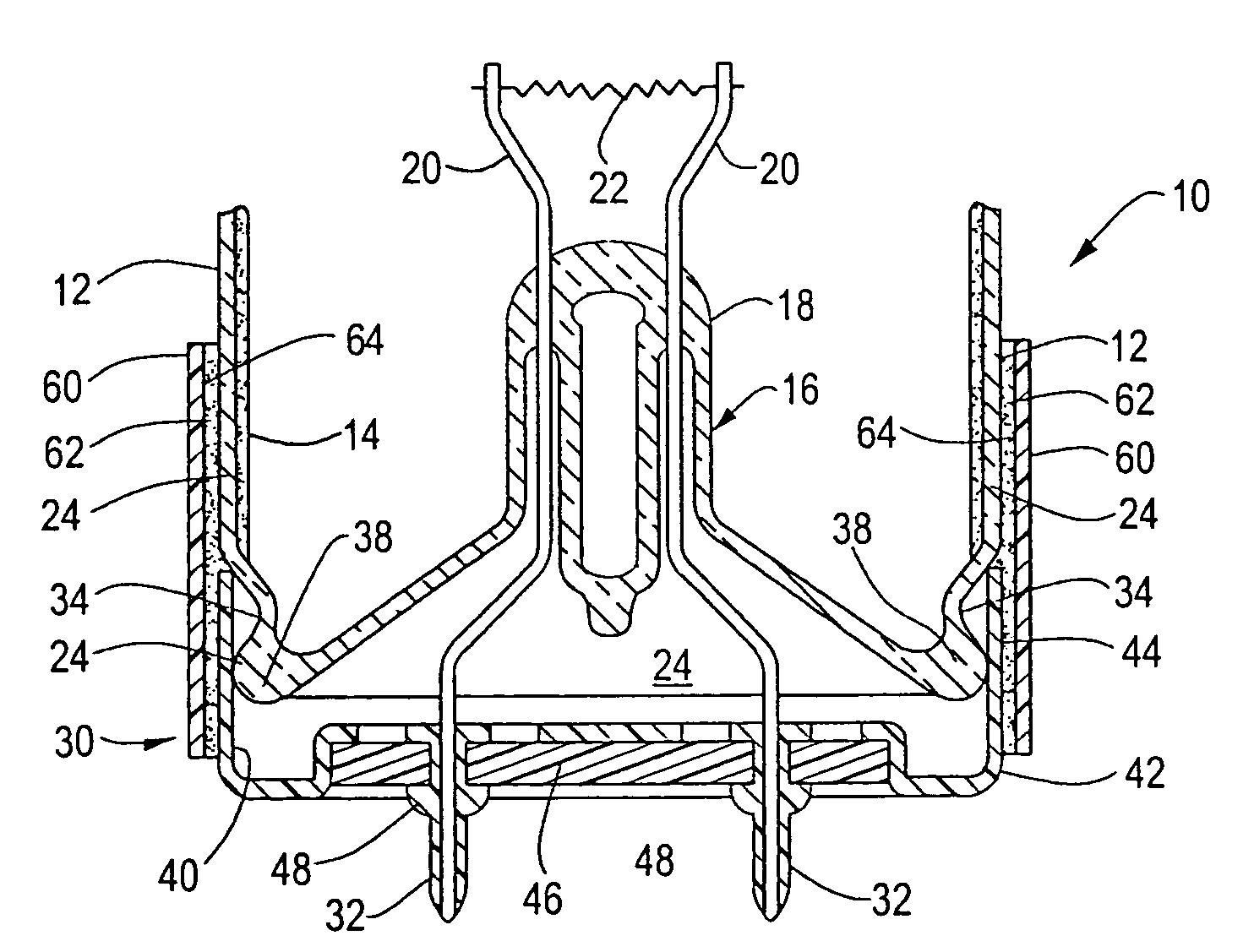
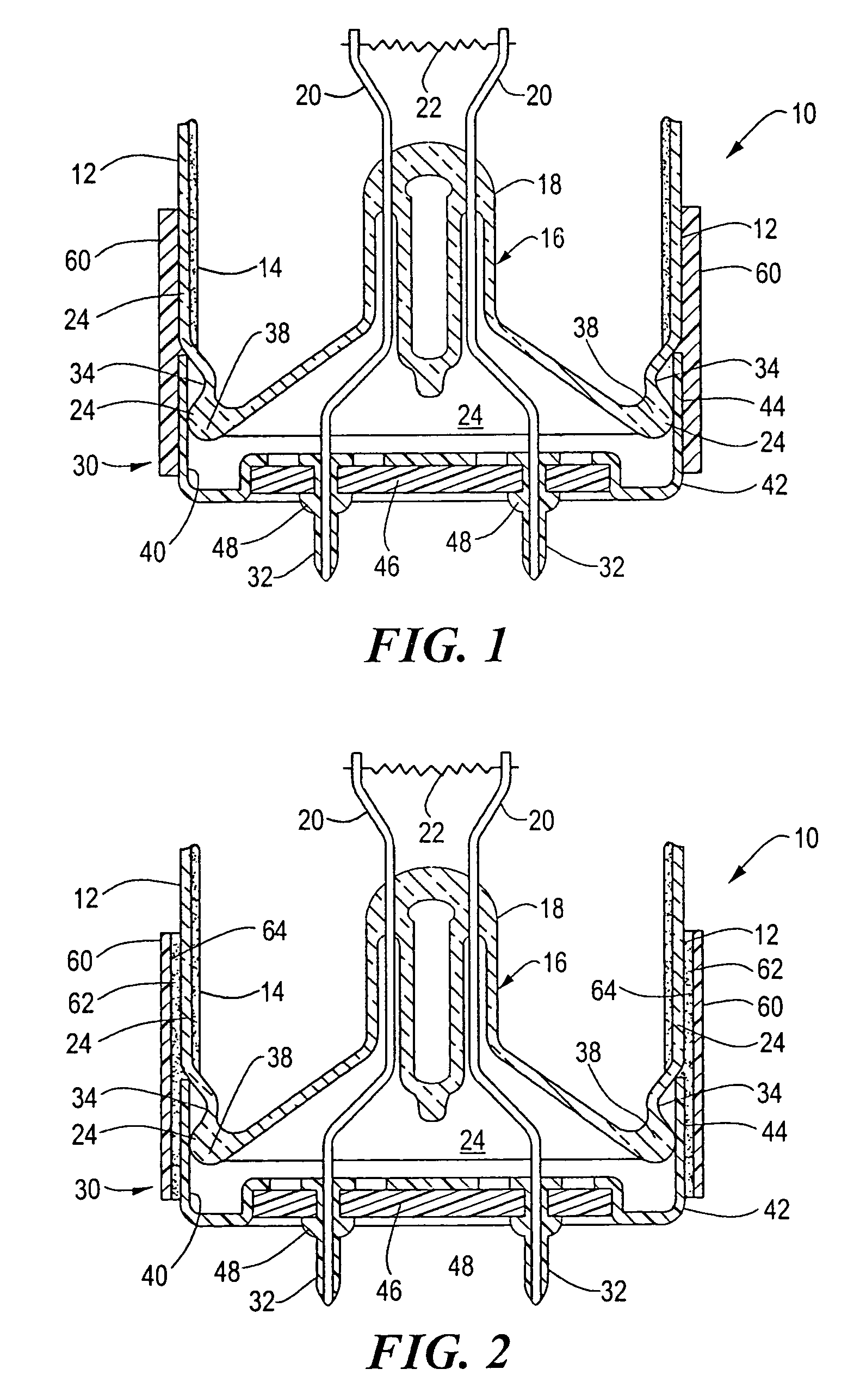
[0025]Referring to FIG. 1, it will be seen that a fluorescent lamp 10 comprising a tubular vitreous or glass envelope 12 is provided with an inner coating of phosphor 14 and is hermetically sealed at each end by a glass mount 16. Each mount 16 includes a stem press 18 within which a pair of lead wires 20 are sealed. A thermionic electrode 22 is mounted on the inner ends of lead wires 20 within the tubular glass envelope 12. Each thermionic electrode 22 comprises a tungsten coil coated with an emissive material of alkaline earth oxides.

[0026]In accordance with standard lamp-making practices, the envelope 12 is filled with a suitable starting gas and doped with mercury to provide an ionizable medium within the sealed envelope, which permits an electric discharge to pass between the thermionic electrodes.

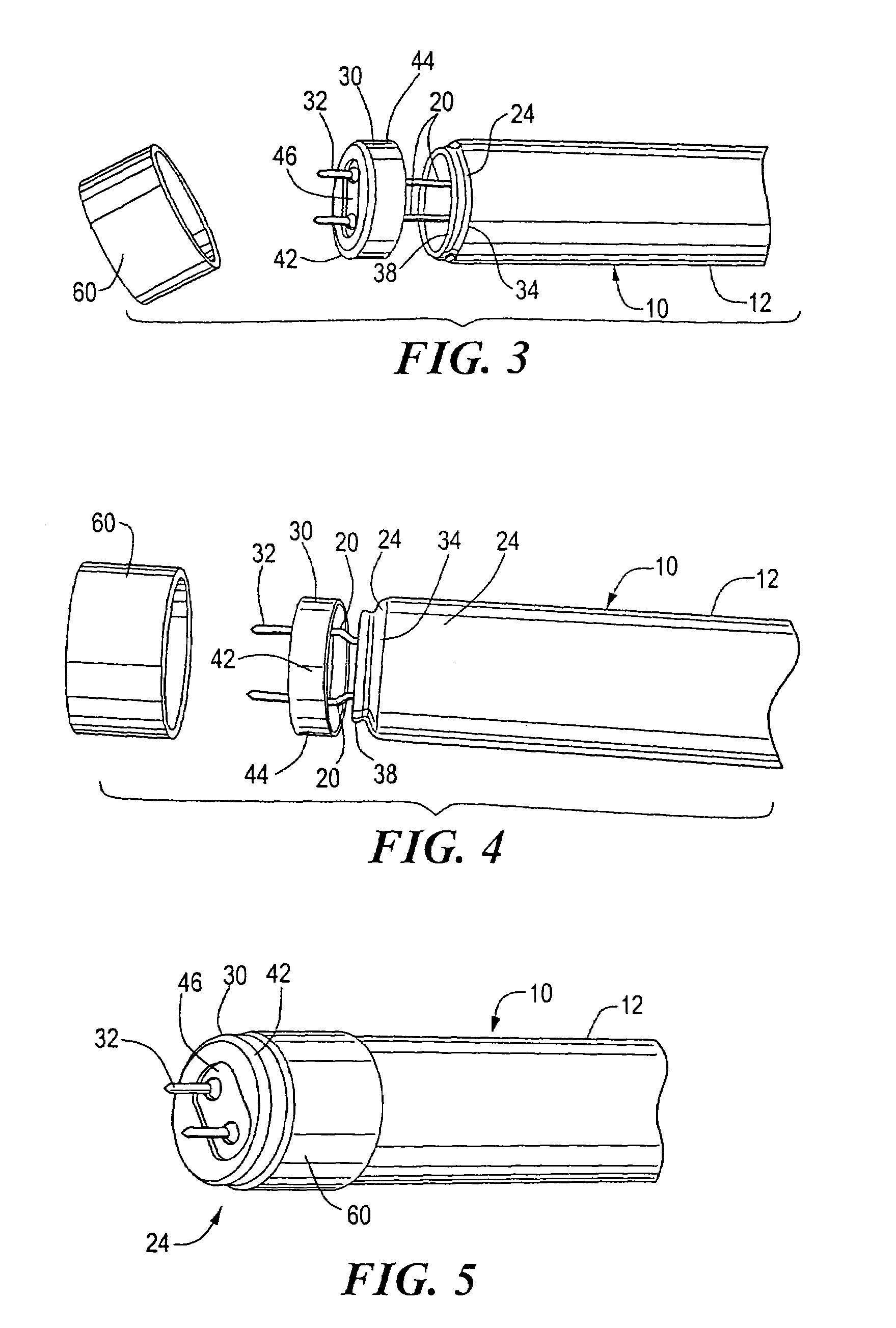
[0027]Each end portion 24 of the lamp envelope 12 may include an annular groove 34 which terminates at an annular rim or seal 38. Each of the sealed end portions 24 of envelope 12 is f...


PUM


Abstract

A fluorescent lamp includes a glass envelope having a sealed end portion, a base shell member of a cup-shape configuration adapted to engage the envelope end portion, and a collar of shrink wrap material disposed around the envelope end portion and sides of the base shell member, the shrink wrap material being shrunken and compressing against the envelope end portion and the base shell member, to fix the base shell member on the envelope end portion.

Description

[0001]This is a division application Ser. No. 10 / 077,254, filed Feb. 15, 2002, now U.S. Pat. No. 6,794,811.BACKGROUND OF THE INVENTION[0002]1. Field of the Invention[0003]The invention relates to fluorescent lamps, and is directed more particularly to a base for such lamps.[0004]2. Description of the Prior Art[0005]In the manufacture of lamps, a lamp envelope is usually provided with at least one base. Generally, a lamp base comprises a rigid shell secured to an end portion of the lamp envelope. At least one insulating disk is fixed in the shell for carrying one or more hollow base pins, or contacts, into which the lamp lead wires are electrically secured. The lamp is supported by one or more holders, or sockets, into which the lamp bases extend for communication with a source of electrical energy.[0006]Typically, such lamp bases are secured to the end portions of the lamp envelope by means of a cement which is applied to the inside surface of a base shell annular wall. A sufficient...

Claims


Application Information

Patent Timeline
IPC IPC(8): H01J9/00H01J5/54H01J5/58
CPCH01J5/58H01J5/54
Inventor CUNKELMAN, GARY T.LAIRD, RICHARD C.
Owner OSRAM SYLVANIA INC
Why Eureka
Try Eureka