Method of determining the long axis of an object

a technology of object longitudinal reference and axis, which is applied in the field of determining the longitudinal reference can solve the problems of difficult precision in visual determination of the facial axis point, the difficulty of determining the long axis of an object that is complex in shape, and the general consideration of teeth as complex in shap

Inactive Publication Date: 2006-04-25
3M INNOVATIVE PROPERTIES CO
View PDF15 Cites 25 Cited by
  • Summary
  • Abstract
  • Description
  • Claims
  • Application Information

AI Technical Summary

Benefits of technology

[0018]The present invention relates to a method of determining the long axis of an object and is especially useful as computer software. The method provides a geometric analysis that is capable of determining the long axis of a variety of objects that are complex in shape, such as teeth. In particular, the method can be used to determine the long axis of a variety of teeth of different types and shapes without the need for subjective input from the practitioner. The method is particularly useful for orthodontic diagnosis and treatment, since the long axes of a patient's teeth can be used in a program that aids in the precise placement of orthodontic appliances on the surfaces of the teeth or that predicts the paths of movement and future positions of the teeth.

Problems solved by technology

However, the long axis of an object that is complex in shape may be substantially more difficult to determine.
For example, teeth are generally considered to be complex in shape.
As another example, if the bracket is placed to one side of the center of the tooth in a mesial-distal direction, the resultant tooth orientation will likely be an orientation that is excessively rotated about its long axis.
Unfortunately, visual determination of the facial axis point is often difficult to carry out with precision and may be subjective in nature.
In practice, however, such a determination is difficult to carry out with a high level of accuracy when a visual assessment is employed.

Method used


Image

  • Method of determining the long axis of an object
  • Method of determining the long axis of an object
  • Method of determining the long axis of an object

Examples


Embodiment Construction

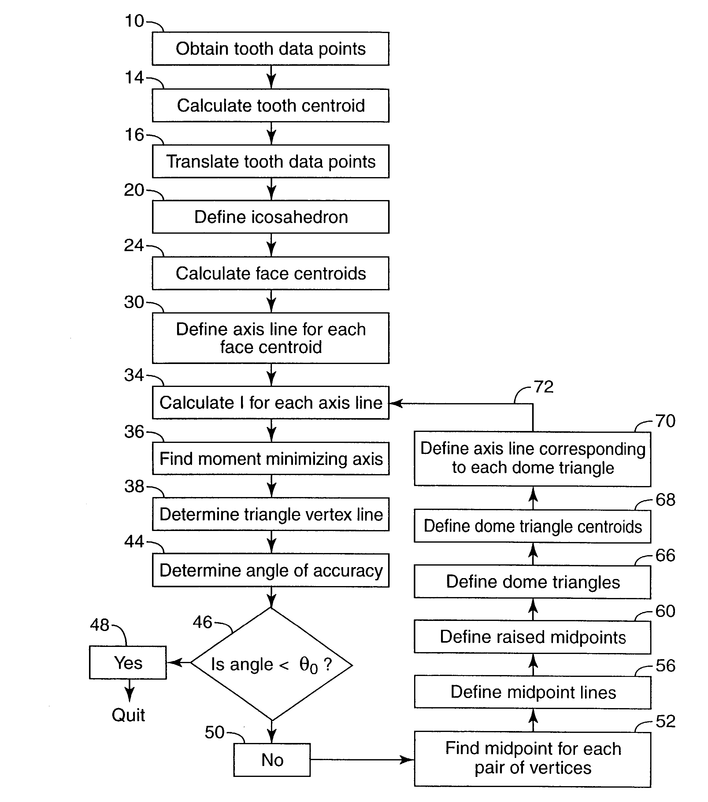
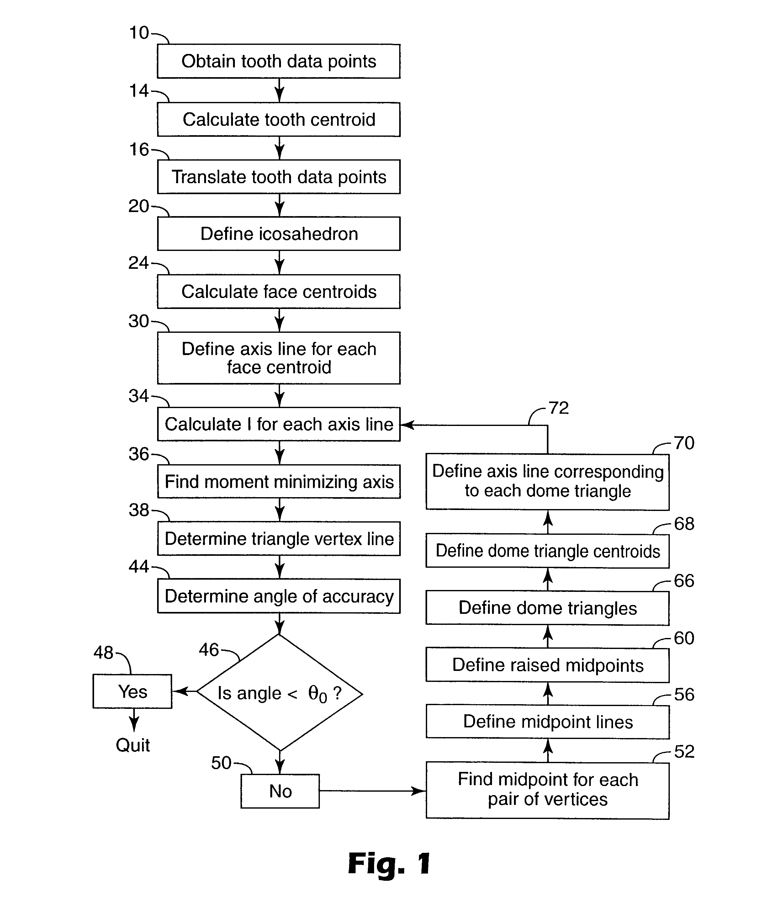
[0055]A method of determining the long axis of an object according to one embodiment of the present invention is set out in the flow chart illustrated in FIG. 1. In the particular embodiment described in FIG. 1, the object is a tooth of a dental patient. However, the present invention may be used to find the long axis of other objects as well.

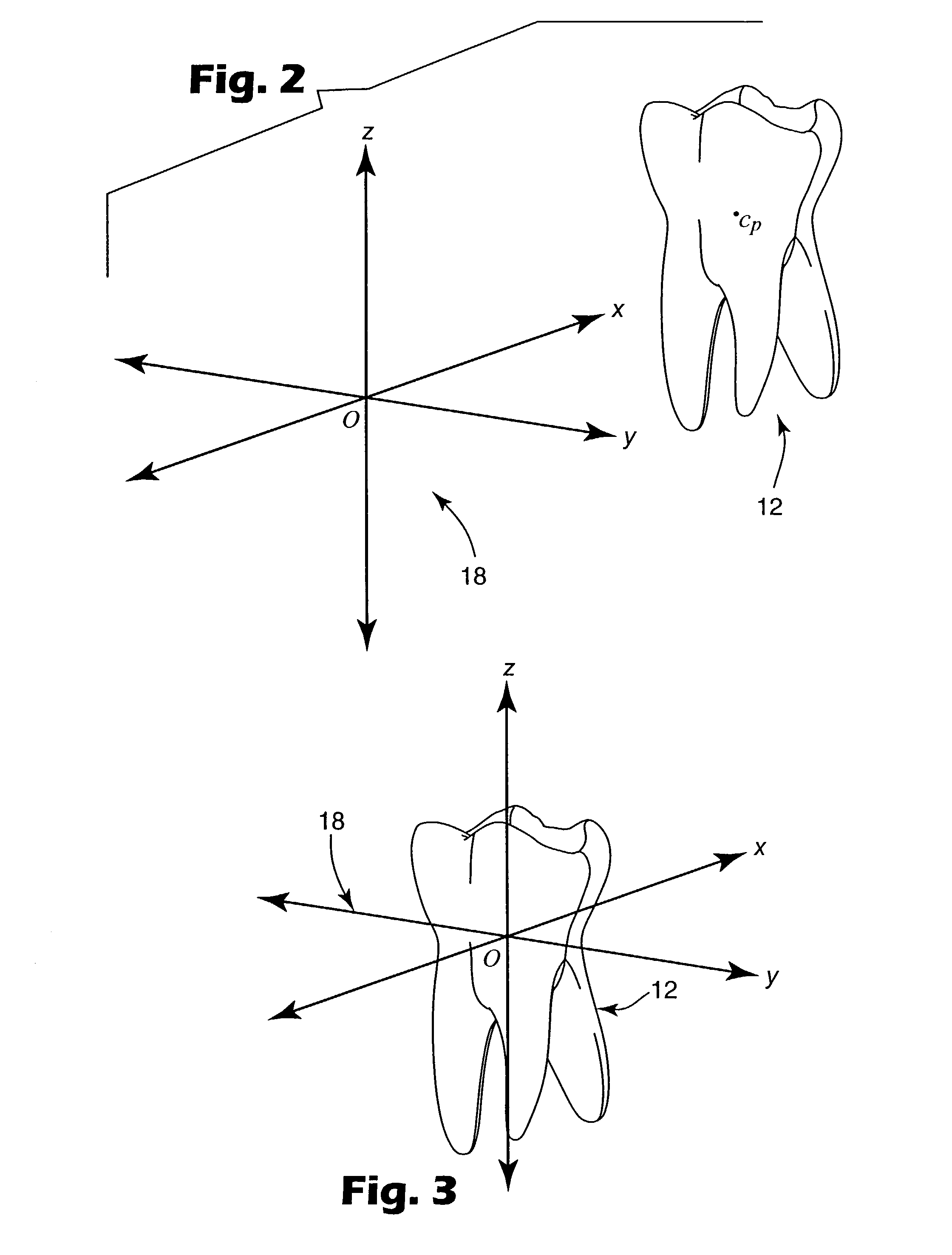
[0056]In FIG. 1, Box 10 describes the act of obtaining a set of data points that represent a tooth. The data points may represent points on the outer surface of the tooth including the crown (i.e., the part normally exposed and not covered by gingiva) as well as the root or roots (i.e., the part normally not exposed). As another option, the data set may represent points that are uniformly or non-uniformly distributed throughout the volume occupied by the tooth. As an additional alternative, the set of data points may represent any combination of the foregoing.

[0057]The data points may be obtained by any suitable method. For example, the data po...


PUM


Abstract

The long axis of an object that is complex in shape, such as a tooth, may be accurately determined using digital data representing the shape of the object. A polyhedron is defined such that the center of the polyhedron coincides with a point representing the centroid of the object. Axis lines are then determined by establishing reference lines through each face of the polyhedron and the point representing the centroid of the object. The moment of the object is calculated about each axis line, and the axis line that corresponds to the smallest calculated moment is selected. Additional iterations of the method are then carried out by recursively subdividing the corresponding face into smaller sections until a desired angular accuracy is achieved. The method is particularly useful for orthodontic diagnosis and treatment.

Description

BACKGROUND OF THE INVENTION[0001]1. Field of the Invention[0002]This invention relates to a method of determining the longitudinal reference axis of an object. The method is particularly suitable for use with a computer software module that finds the long axis of a tooth as part of an orthodontic diagnosis and treatment analysis.[0003]2. Description of the Related Art[0004]The longitudinal axis, or long axis, of objects that are relatively simple in shape is often easy to determine. For example, the long axis of an object having a uniform circular or rectangular shape in transverse cross-sections can be derived by extending a reference line perpendicularly through the center of the cross-sections. However, the long axis of an object that is complex in shape may be substantially more difficult to determine.[0005]For example, teeth are generally considered to be complex in shape. The exposed portion of each tooth, also known as the clinical crown, varies widely from tooth to tooth. Fo...

Claims


Application Information

Patent Timeline
Patent Type & Authority Patents(United States)
IPC IPC(8): A61B5/103A61B5/117A61C19/04G06T7/00G06T7/60
CPCG06T7/606G06T7/0042A61C2007/004G06T2207/30036G06T7/73G06T7/66A61B5/103
Inventor RABY, RICHARD E.
Owner 3M INNOVATIVE PROPERTIES CO
Why Eureka
Try Eureka