Electrosurgical electrode having a non-conductive porous ceramic coating

a porous ceramic, electrode technology, applied in the field of electrosurgical electrodes, can solve the problems of difficult prediction and control of the depth of ablation, and the inability of known electrodes to control or limit the current per arc, so as to improve the arc distribution across the tissue, the effect of improving the arc distribution

Active Publication Date: 2006-04-25
COVIDIEN AG
View PDF389 Cites 265 Cited by
  • Summary
  • Abstract
  • Description
  • Claims
  • Application Information

AI Technical Summary

Benefits of technology

[0011]This has the effect of separating the arc current, effectively increasing the current frequency, resulting in a finer cut or other surgical effect. That is, the non-conductive, porous ceramic coating enables the application of a low frequency current to achieve surgical results indicative of a high frequency current, while minimizing or preventing thermal damage to adjacent tissue.
[0013]The diameter of each pore can vary from the diameter of other pores to produce different surgical effects when operating the electrosurgical generator system in one of several modes, such as cut, blend and coagulation modes. In either embodiment, MCD enables the surgeon to control the proportion of tissue vaporization to tissue heating, in order to achieve more controllable and desirable surgical effects.
[0015]Alternative embodiments provide for the non-conductive, porous ceramic coating to be applied to roller-ball type electrodes for improving the arc distribution across the tissue, and hence, the efficiency of the electrode, as compared to roller-ball type electrodes not coated with the non-conductive, porous ceramic material. Other embodiments and features include modifying the geometry of the electrode before applying the non-conductive, porous ceramic coating on the electrode, so as to control where the arc is split and / or cutting / coagulating occurs, i.e., along edge of the electrode, along length of the electrode, across width of the electrode, etc.

Problems solved by technology

As can be appreciated, by not controlling the thermal spread the depth of ablation is difficult to predict and control.
Known electrodes cannot control or limit the current per arc to achieve a particular surgical effect, e.g., a fine cut.

Method used


Image

  • Electrosurgical electrode having a non-conductive porous ceramic coating
  • Electrosurgical electrode having a non-conductive porous ceramic coating
  • Electrosurgical electrode having a non-conductive porous ceramic coating

Examples


Embodiment Construction

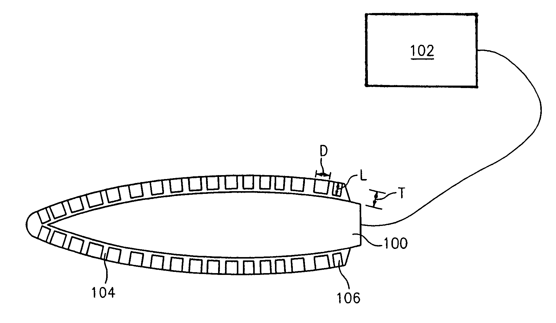
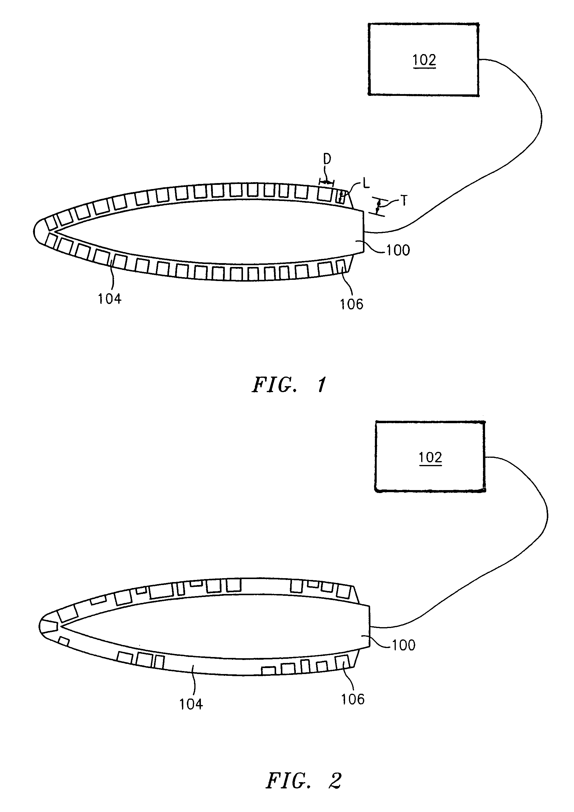
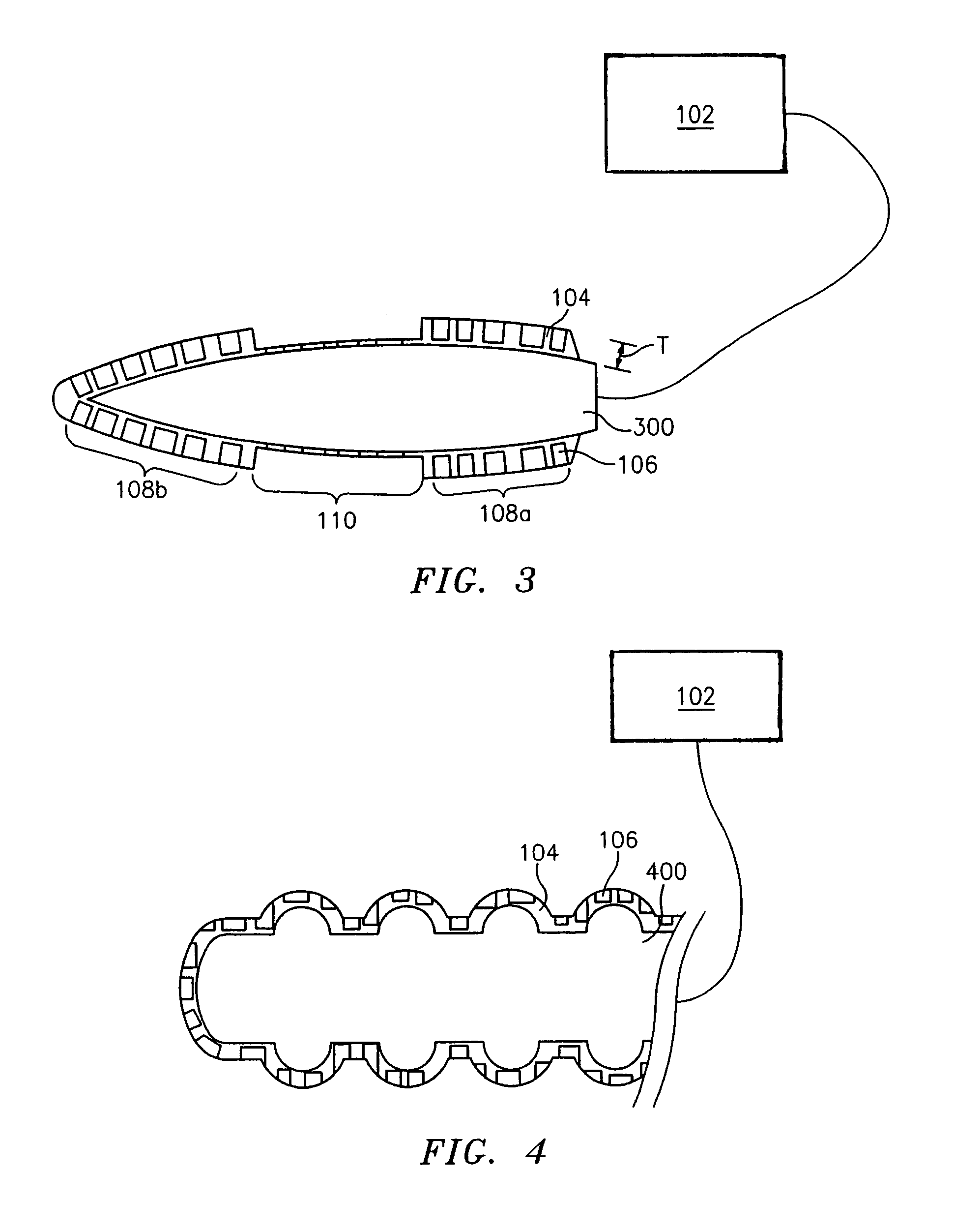
[0027]Reference should be made to the drawings where like reference numerals refer to similar elements. Referring to FIG. 1, there is shown an enlarged, cross-sectional view of one embodiment of a conductive electrode according to the present disclosure. The electrode is designated generally by reference numeral 100 and it is connected to an electrosurgical generator system 102. The electrode 100 is coated with a non-conductive, porous ceramic coating 104 which “pinches” or splits the arc current generated by the electrosurgical generator system 102 into a small diameter channel, effectively keeping the same current and voltage, but creating several small arcs from one large arc.

[0028]This has the effect of separating the arc current, effectively increasing the current effect to the tissue, resulting in a finer cut or other surgical effect. That is, the non-conductive, porous ceramic coating 104 enables a low frequency current to achieve surgical results indicative of a high frequen...


PUM

PropertyMeasurementUnit
diameteraaaaaaaaaa
frequencyaaaaaaaaaa
lengthaaaaaaaaaa

Abstract

An electrosurgical electrode and electrosurgical generator system utilizing the same are disclosed capable of controlling or limiting the current per arc in real-time during an electrosurgical procedure. The conductive electrosurgical electrode is configured for being connected to an electrosurgical generator system and has a non-conductive, porous ceramic coating that “pinches” or splits the arc current generated by the electrosurgical generator system into the smaller diameter pores of the coating, effectively keeping the same current and voltage, but creating several smaller diameter arcs from one larger diameter arc. This has the effect of separating the arc current, effectively increasing the current frequency, resulting in a finer cut or other surgical effect. That is, the non-conductive, porous ceramic coating enables a low frequency current to achieve surgical results indicative of a high frequency current, while minimizing or preventing thermal damage to adjacent tissue.

Description

CROSS REFERENCE TO RELATED APPLICATIONS[0001]This application claims the benefit of priority to U.S. Provisional Application Ser. No. 60 / 432,385 filed on Dec. 10, 2002, the entire contents of which are hereby incorporated by reference herein.BACKGROUND[0002]1. Technical Field[0003]The present disclosure is directed to electrosurgery and, in particular, to an electrosurgical electrode having a non-conductive porous ceramic coating for controlling the amount of current per arc.[0004]2. Description of the Related Art[0005]Tissue heating is proportional to the square of the amount of current being generated through the tissue and tissue vaporization is, in turn, generally proportional to current. Vaporization of tissue is proportional to the amount of energy in the arc. This energy, in combination with the Cathode Fall Voltage, derives the power for vaporization. Thermal spread is dependent on the amount of heat generated within the tissue and is dependent on tissue resistivity and the ...

Claims


Application Information

Patent Timeline
Patent Type & Authority Patents(United States)
IPC IPC(8): A61B18/14
CPCA61B18/14A61B2017/0088A61B2018/1213A61B2018/00083A61B2018/00107A61B2018/00065
Inventor KEPPEL, DAVID S.
Owner COVIDIEN AG
Why Eureka
Try Eureka