Microcoil vaso-occlusive device with multi-axis secondary configuration

a vaso-occlusive device and micro-coil technology, applied in the field of vascular occlusion devices and methods, can solve the problems of balloon rupture during inflation, difficult visualization, and difficult to retrieve or move after solidifying fluid sets, and achieve the effect of minimizing shifting or tumbling and minimizing the degree of compaction experienced

Inactive Publication Date: 2006-04-25
MICROVENTION INC
View PDF60 Cites 81 Cited by
  • Summary
  • Abstract
  • Description
  • Claims
  • Application Information

AI Technical Summary

Benefits of technology

[0019]In any of the embodiments, the device, in its minimum energy state secondary configuration, has a dimension that is substantially larger (preferably at least about 25% greater) than the largest dimension of the vascular space in which the device is to be deployed. Most preferably, the length of the device, in its minimum energy state secondary configuration, should be at least about twice the maximum diameter of the targeted aneurysm or other vascular site in which the device is to be installed. Also, it is advantageous to provide in the device at least one curved segment having a diameter, in the minimum energy state secondary configuration, that is approximately equal to the largest diameter of the targeted aneurysm or vascular site. Thus, when the device is deployed inside a vascular site such as an aneurysm, the confinement of the device within the site causes the device to assume a three-dimensional configuration that has a higher energy state than the minimum energy state. Because the minimum energy state of the device is larger (in at least one dimension) than the space in which it is deployed, the deployed device is constrained by its intimate contact with the walls of the aneurysm from returning to its minimum energy state configuration. Therefore, the device still engages the surrounding aneurysm wall surface, thereby minimizing shifting or tumbling due to blood flow dynamics. Furthermore, the minimum energy state secondary configuration (to which the device attempts to revert) is not one that is conducive to “coin stacking”, thereby minimizing the degree of compaction that is experienced.

Problems solved by technology

While the balloon-type embolization device can provide an effective occlusion of many types of aneurysms, it is difficult to retrieve or move after the solidifying fluid sets, and it is difficult to visualize unless it is filled with a contrast material.
Furthermore, there are risks of balloon rupture during inflation and of premature detachment of the balloon from the catheter.
The direct injection of liquid polymer embolic agents has proven difficult in practice.
For example, migration of the polymeric material from the aneurysm and into the adjacent blood vessel has presented a problem.
In addition, visualization of the embolization material requires that a contrasting agent be mixed with it, and selecting embolization materials and contrasting agents that are mutually compatible may result in performance compromises that are less than optimal.
Furthermore, precise control of the deployment of the polymeric embolization material is difficult, leading to the risk of improper placement and / or premature solidification of the material.
Moreover, once the embolization material is deployed and solidified, it is difficult to move or retrieve.
While many prior art microcoil devices have met with some success in treating small aneurysms with relatively narrow necks, it has been recognized that the most commonly used microcoil vaso-occlusive devices achieve less than satisfactory results in wide-necked aneurysms, particularly in the cerebrum.
There has thus been a long-felt, but as yet unsatisfied need for a microcoil vaso-occlusive device that has the advantages of many of the prior art microcoil devices, but that can be used effectively to treat aneurysms of many different sizes configurations, and in particular those with large neck widths.

Method used


Image

  • Microcoil vaso-occlusive device with multi-axis secondary configuration
  • Microcoil vaso-occlusive device with multi-axis secondary configuration
  • Microcoil vaso-occlusive device with multi-axis secondary configuration

Examples


Embodiment Construction

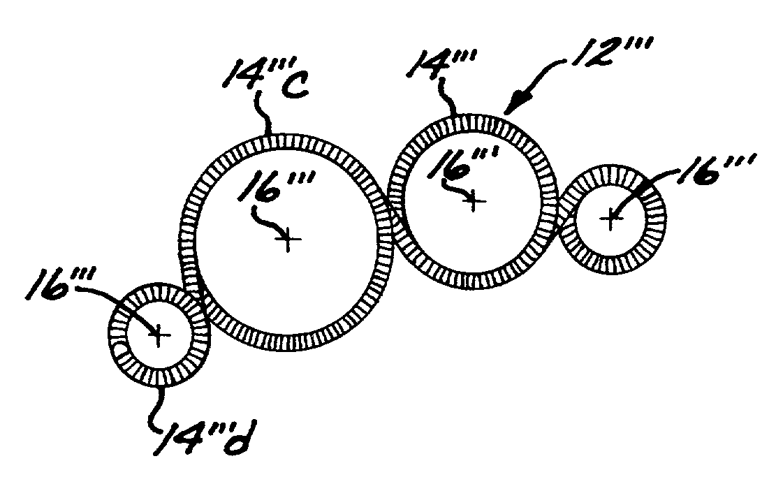
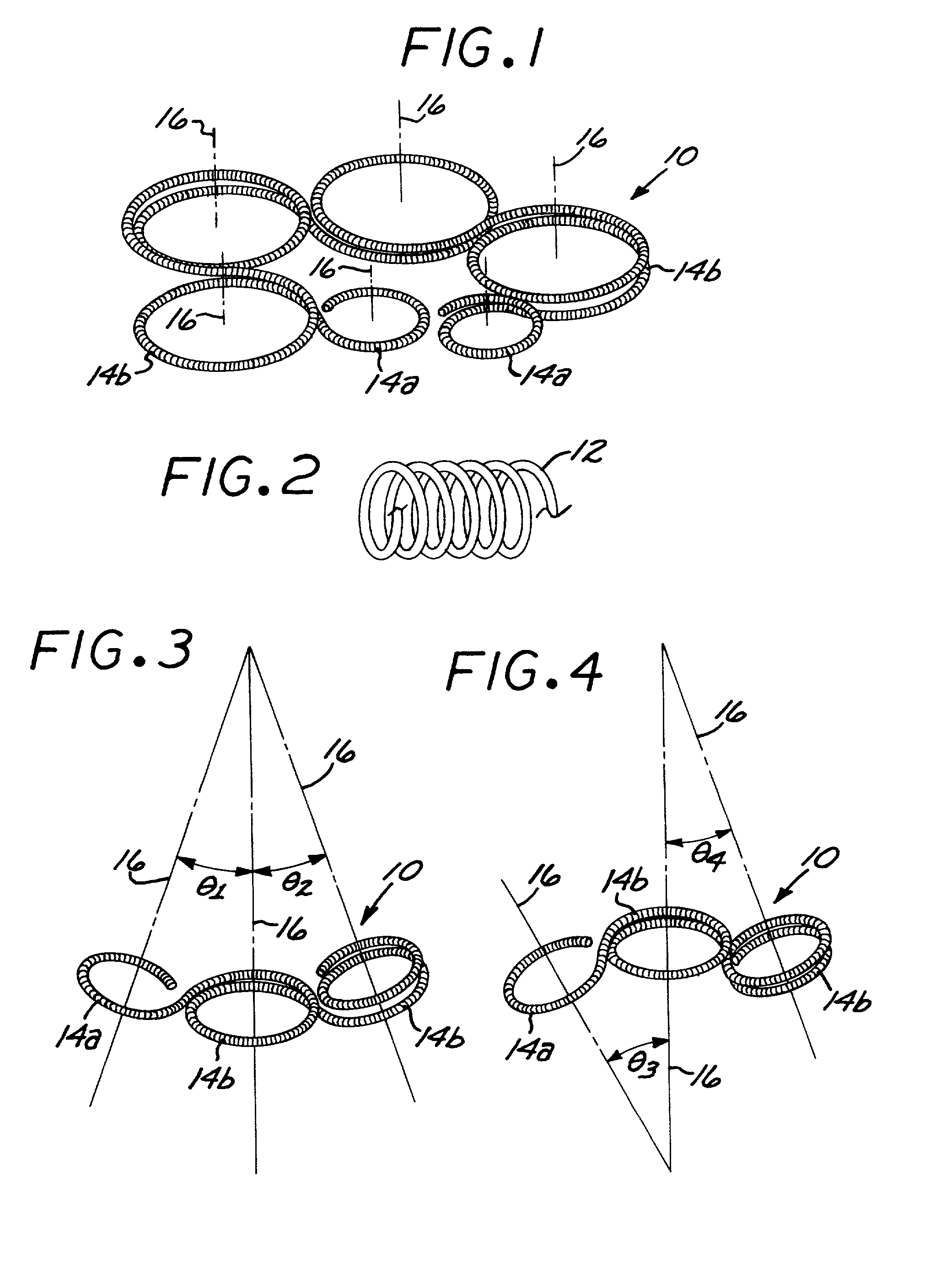
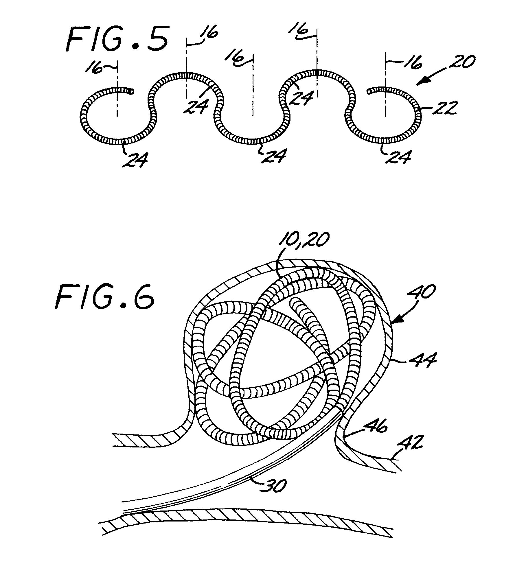
[0034]Referring first to FIGS. 1–4 and 8, a microcoil vaso-occlusive device 10, in accordance with a preferred embodiment of the invention is shown. The device 10 comprises a suitable length of wire formed into the primary configuration of a helical microcoil 12 (FIG. 2). Suitable materials for the device 10 include platinum, rhodium, palladium, rhenium, tungsten, gold, silver, tantalum, and various alloys of these metals. Various surgical grade stainless steels may also be used. Preferred materials include the platinum / tungsten alloy known as Platinum 479 (92% Pt, 8% W, available from Sigmund Cohn, of Mount Vernon, N.Y.) and titanium / nickel alloys (such as the titanium / nickel alloy known as “nitinol”). Another material that may be advantageous is a bimetallic wire comprising a highly elastic metal with a highly radiopaque metal. Such a bimetallic wire would also be resistant to permanent deformation. An example of such a bimetallic wire is a product comprising a nitinol outer layer...


PUM


Abstract

A vaso-occlusive device includes a microcoil formed into a minimum energy state secondary configuration comprising a plurality of curved segments, each defining a discrete axis, whereby the device, in its minimum energy state configuration, defines multiple axes. In a preferred embodiment, the secondary configuration-comprises a plurality of interconnected closed loops defining a plurality of discrete axes. In a second embodiment, the secondary configuration defines a wave-form like structure comprising an array of laterally-alternating open loops defining a plurality of separate axes. In a third embodiment, the secondary configuration forms a series of tangential closed loops, wherein the entire structure subtends a first angle of arc, and wherein each adjacent pair of loops defines a second angle of arc. In a fourth embodiment, the secondary configuration forms a logarithmic spiral. In all embodiments, the device, in its secondary configuration, has a dimension that is substantially larger than the largest dimension of the vascular site (i.e., aneurysm) in which it is to be deployed. Thus, confinement of the device within an aneurysm causes it to assume a three-dimensional configuration with a higher energy state than the minimum energy state. Because the minimum energy state configuration of the device is larger (in at least one dimension) than the aneurysm, the deployed device is constrained by its contact with the walls of the aneurysm from returning to its minimum energy state configuration. The engagement of the device with the aneurysm wall minimizes shifting or tumbling due to blood flow. Furthermore, the secondary configuration is not conducive to “coin stacking,” thereby minimizing the compaction experienced.

Description

CROSS-REFERENCE TO RELATED APPLICATIONS[0001]This application is a Continuation-in-Part of application Ser. No. 09 / 671,021; filed Sep. 26, 2000 now U.S. Pat. No. 6,605,101.FEDERALLY-SPONSORED RESEARCH OR DEVELOPMENT[0002]Not ApplicableBACKGROUND OF THE INVENTION[0003]This invention relates generally to the field of vascular occlusion devices and methods. More specifically, it relates to an apparatus and method for occluding a blood vessel by embolizing a targeted site (such as an aneurysm) in the blood vessel.[0004]The embolization of blood vessels is desired in a number of clinical situations. For example, vascular embolization has been used to control vascular bleeding, to occlude the blood supply to tumors, and to occlude vascular aneurysms, particularly intracranial aneurysms. In recent years, vascular embolization for the treatment of aneurysms has received much attention. Several different treatment modalities have been employed in the prior art. U.S. Pat. No. 4,819,637—Dorman...

Claims


Application Information

Patent Timeline
Patent Type & Authority Patents(United States)
IPC IPC(8): A61M29/00A61B17/00A61B17/12
CPCA61B17/12022A61B17/12113A61B17/12145A61B2017/00867A61B2017/00526
Inventor SCHAEFER, DEANCOX, BRIAN J.GREENE, JR., GEORGE R.FERRERA, DAVID A.FITZ, MATTHEWROSENBLUTH, ROBERT F.
Owner MICROVENTION INC
Why Eureka
Try Eureka