Centrifugal separator

Inactive Publication Date: 2006-04-25
MANN HUMMEL GMBH
View PDF7 Cites 44 Cited by
  • Summary
  • Abstract
  • Description
  • Claims
  • Application Information

AI Technical Summary

Benefits of technology

[0007]According to the invention, the housing of the centrifugal separator is non-rotatably mounted. Inside the housing, an impeller equipped with blades that produce a centrifugal flow is arranged so as to be rotatable about the longitudinal axis of the drive shaft. As a result, the gas outlet formed in the housing does not need to be sealed against parts moving in relation thereto. The impeller rotates in the housing without contact, which prevents relative movements and the wear connected therewith. At the same time, a simple construction of the centrifugal separator is obtained.
[0008]Advantageously, the gas inlet is disposed at the circumference of the drive shaft between housing and drive shaft and surrounds the drive shaft completely. The gas is admitted approximately parallel to the longitudinal axis of the drive shaft. The gas inlet formed at the circumference of the drive shaft is simple to manufacture and enables a uniform inflow of the gas to be purified.
[0009]The gas inlet and the gas outlet are advantageously disposed on opposite sides of a separating wall extending perpendicularly to the longitudi

Problems solved by technology

The required seal, however,

Method used


Image

  • Centrifugal separator
  • Centrifugal separator

Examples


Example

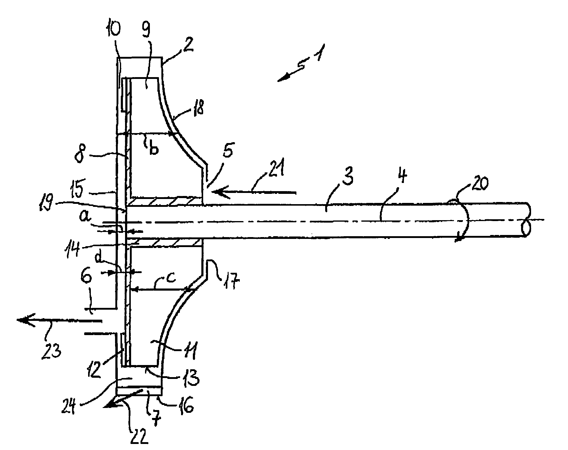
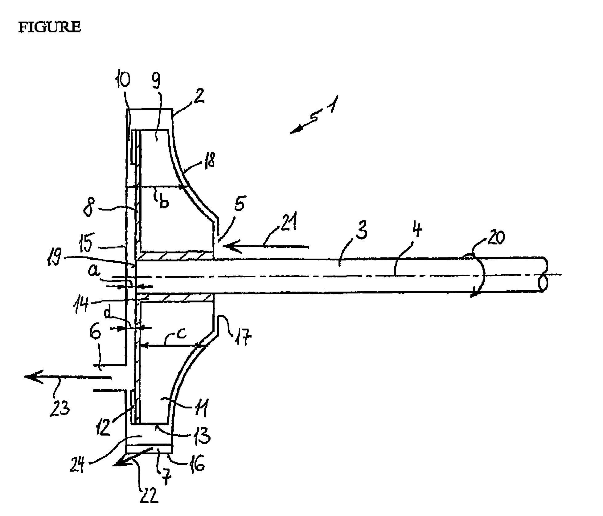
[0014]The centrifugal separator 1 illustrated in the FIGURE comprises a housing 2, which is fixed against rotation. Desirably, housing 2 may be formed on the cylinder head of an internal combustion engine. The housing 2 is largely rotationally symmetrical to the longitudinal axis 4 of a drive shaft 3.

[0015]The housing 2 has a front wall 18 that is curved in the direction of the longitudinal axis 4 of the drive shall 3. The longitudinal axis 4 simultaneously represents the axis of symmetry of the housing 2. In the area of the drive shaft 3, the front wall 18 of the housing 2 has an opening 17, particularly a circular opening, disposed concentrically to the longitudinal axis 4. The drive shaft 3 projects into the housing 2 through this opening 17. Between the drive shaft 3 and the housing 2, there is a space extending circularly between the outer circumference of the drive shaft 3 and the opening 17 and forming the gas inlet 5.

[0016]Within the housing 2, an impeller 14 is non-rotatabl...


PUM

PropertyMeasurementUnit
Flow rateaaaaaaaaaa
Widthaaaaaaaaaa
Areaaaaaaaaaaa

Abstract

A centrifugal separator for separating oil from a gas stream, particularly for venting the crankcase of an internal combustion engine, having a housing (2) in which the flow guiding means are arranged. The flow guiding means are connected to a drive shaft (3). A gas inlet (5) opens into the housing (2), and a gas outlet (6) and an oil outlet (7) lead out of the housing (2). An easily produced and functionally reliable arrangement is obtained if the housing (2) is non-rotatably mounted and an impeller (14) with blades (11) that produce a centrifugal flow is disposed in the housing (2) such that it is rotatable about the longitudinal axis (4) of the drive shaft (3).

Description

BACKGROUND OF THE INVENTION[0001]The invention relates to a centrifugal separator for separating oil from a gas stream, particularly for venting the crankcase of an internal combustion engine.[0002]Published German Patent Application No. DE 198 03 872 discloses a centrifugal separator with a housing in which baffles are arranged to redirect the flow. The centrifugal separator is firmly connected to a drive shaft by which it is driven for rotation. To separate the purified gas from the gas to be purified, it is necessary to seal the rotating housing relative to the adjacent fixed components. The required seal, however, involves the risk of leakage.SUMMARY OF THE INVENTION[0003]It is an object of the invention to provide an improved centrifugal separator for separating contaminants from a gas stream.[0004]Another object of the invention is to provide an effective centrifugal separator having a simple construction.[0005]A further object of the invention is to provide a centrifugal sepa...

Claims


Application Information

Patent Timeline
IPC IPC(8): B01D45/14F01M13/04
CPCF01M13/04Y10S55/19F01M2013/0422
Inventor HILPERT, TORSTENTRAUTMANN, PIUS
Owner MANN HUMMEL GMBH
Why Eureka
Try Eureka