
Holdup time extender and inrush current eliminator for switching power supplies

Inactive Publication Date: 2006-04-25
NETWORK APPLIANCE INC
View PDF6 Cites 10 Cited by
  • Summary
  • Abstract
  • Description
  • Claims
  • Application Information

AI Technical Summary

Benefits of technology

[0004]Accordingly, the present invention is directed to a method and system for supplementing input power during a power failure that minimizes the amount of inrush current upon resumption of input power. In an embodiment of the invention, supplemental power circuitry may include a rechargeable battery that may supply power during a power failure without generating a large inrush current when input power is regained. In an advantageous aspect of the present invention, the supplemental power circuitry of the present invention may provide power for a period of time greater than conventional circuitry, providing power for a period of time greater than twenty milliseconds and may be greater than two minutes depending upon a selected battery capacity.

Problems solved by technology

When large capacitors are utilized to supplement input power for short power failures, a large inrush current is produced when input power is regained.
This requires additional circuitry, typically an inrush current limiting resistor and a relay or transistor with control circuitry, to accommodate the inrush current which adds cost to the power supply.
The incorporation of UPS equipment with a power supply also adds cost to the power supply.

Method used


Image

  • Holdup time extender and inrush current eliminator for switching power supplies
  • Holdup time extender and inrush current eliminator for switching power supplies
  • Holdup time extender and inrush current eliminator for switching power supplies

Examples


Embodiment Construction

[0010]Reference will now be made in detail to the presently preferred embodiments of the invention, examples of which are illustrated in the accompanying drawings.

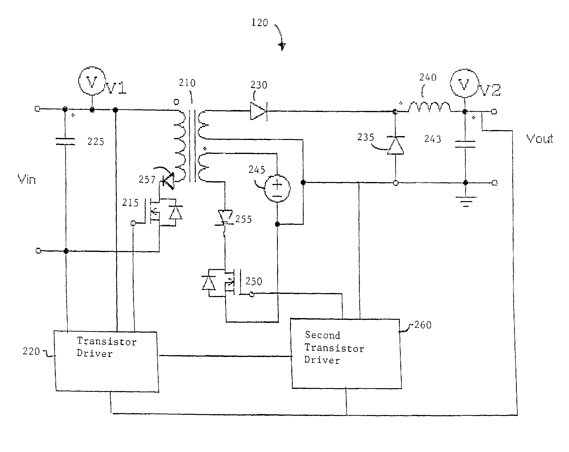
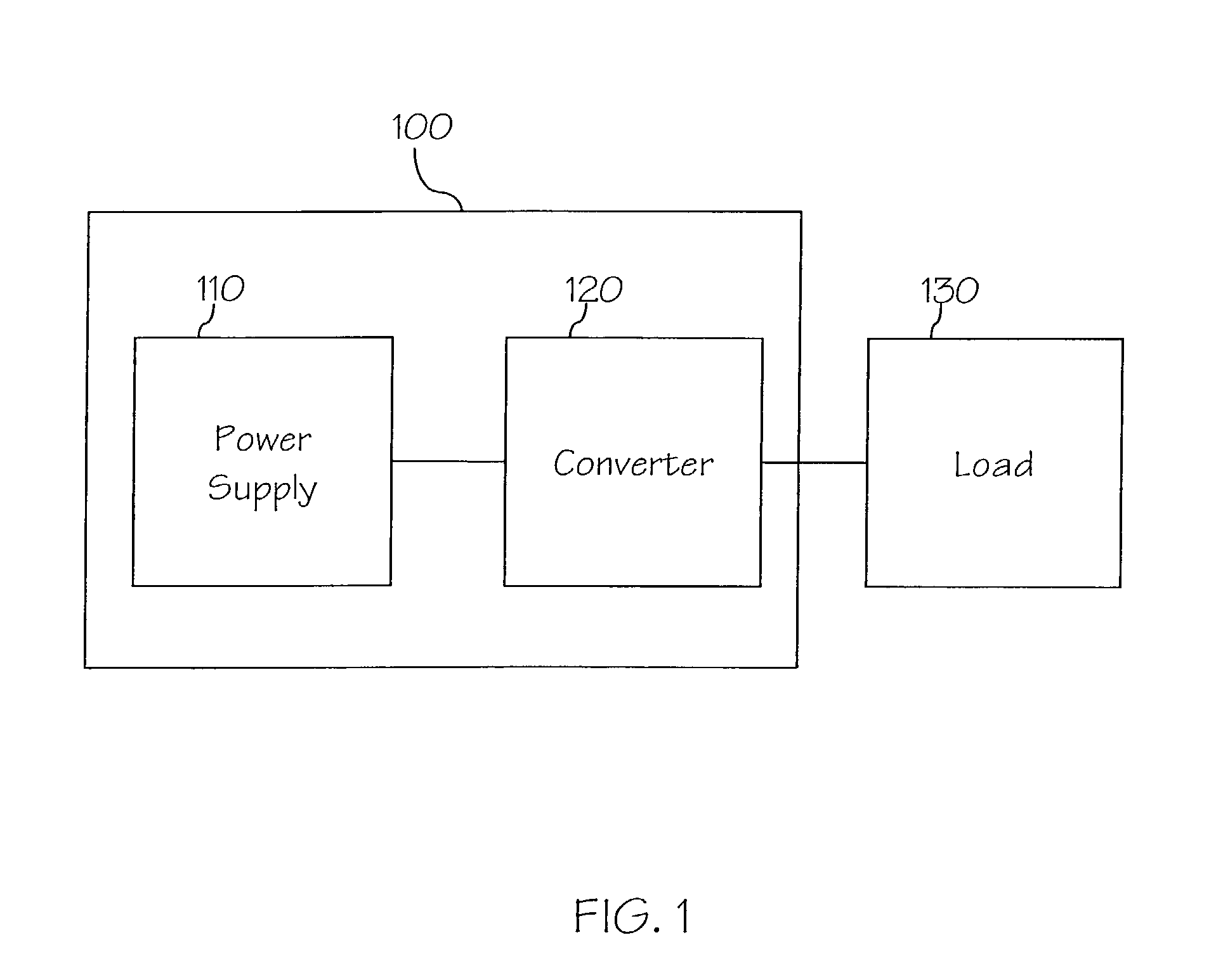
[0011]Referring to FIG. 1, a power supply system 100 in accordance with an embodiment of the present invention is shown. In an embodiment of the invention, power supply system 100 may include a power supply 110 and a converter 120 and is capable of providing a desired supply to load 130. Power supply 110 may produce alternating current (AC) power and direct current (DC) power. In an embodiment of the invention, power supply 110 may be a switching power supply that may utilize power semiconductor switches in the on and off switching states.

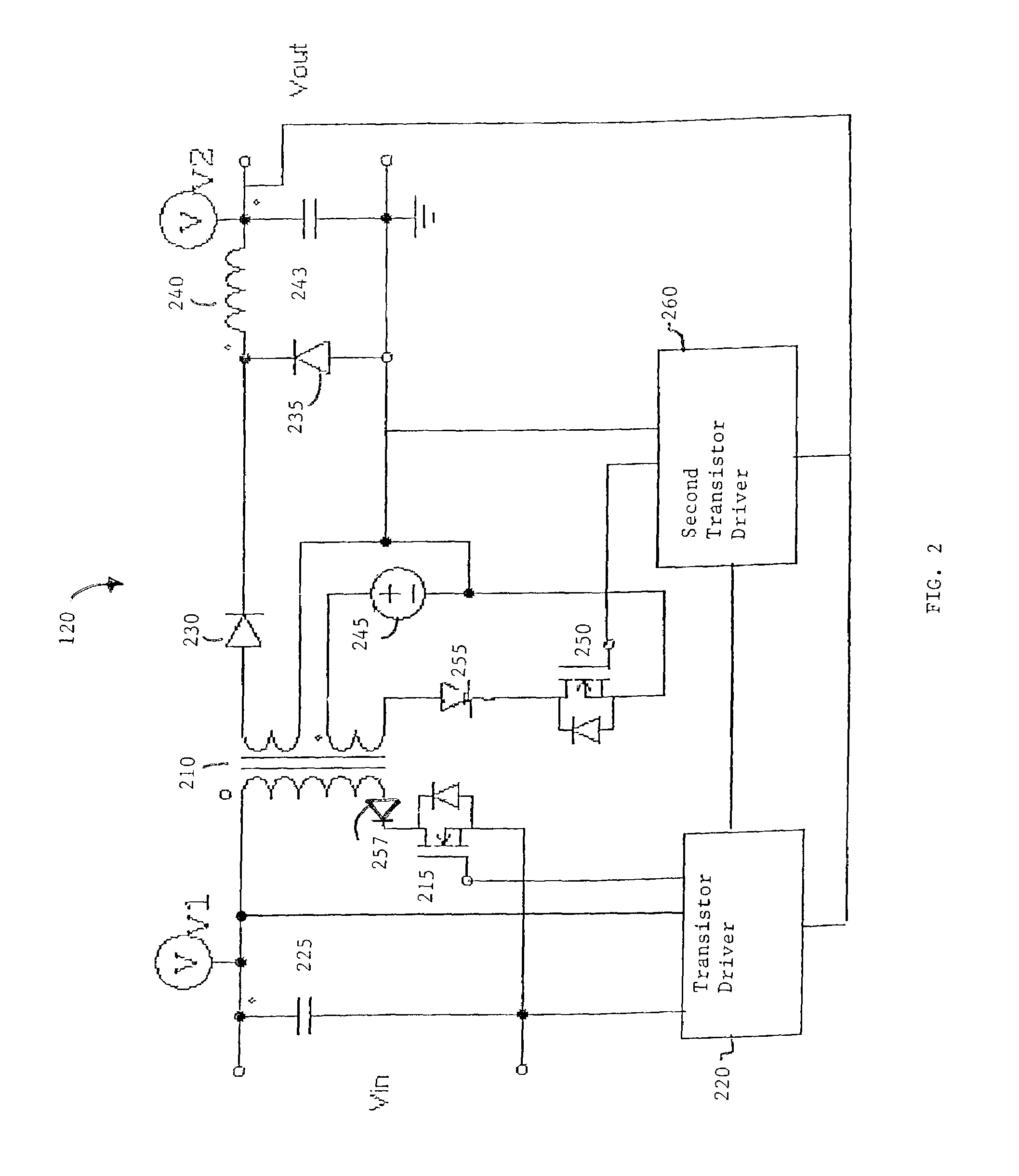
[0012]Converter 120 may be utilized to convert an AC supply to a DC supply and may also convert an unregulated DC supply to a regulated or variable DC supply. In an embodiment of the invention, converter 120 may be a forward converter suitable for conversion of high power. Converter 120, ...


PUM


Abstract

The present invention is a method and system for supplementing power when a power supply has a power failure. An amount of inrush current produced upon resumption of input power is reduced. Supplemental power circuitry may include a rechargeable battery that may supply power during a power failure without generating a large inrush current when input power is regained. The period of time supplemental power may be provided is also increased.

Description

FIELD OF THE INVENTION[0001]The present invention generally relates to the field of power supplies, and more particularly to a method and system for extending the holdup time and reducing the inrush current of a power supply.BACKGROUND OF THE INVENTION[0002]Conventional power supplies known to the art typically employ two methods of recovery during a power failure. For a short input power failure (typically less than 20 milliseconds), large capacitors may be utilized with a converter to supplement input power. When an input power supply is interrupted for a period of greater than 20 milliseconds, uninterruptable power supply (UPS) equipment external to the power supply is necessary.[0003]When large capacitors are utilized to supplement input power for short power failures, a large inrush current is produced when input power is regained. This requires additional circuitry, typically an inrush current limiting resistor and a relay or transistor with control circuitry, to accommodate t...

Claims


Application Information

Patent Timeline
IPC IPC(8): H02J7/00
CPCH02J9/061H02M3/33546H02J2009/067H02J9/067
Inventor ZANSKY, ZOLTANJACOBSEN, BILL
Owner NETWORK APPLIANCE INC
Learn More