Pulsed dynamic keeper gating

a dynamic keeper and keeper technology, applied in the field of dynamic circuits, can solve the problems of circuit producing incorrect output values at the output node, static leakage current exists, and weak keeper may be too large to counteract, so as to reduce the effect of effective keeper circuit strength and protection from nois

Inactive Publication Date: 2006-04-25
ORACLE INT CORP
View PDF9 Cites 22 Cited by
  • Summary
  • Abstract
  • Description
  • Claims
  • Application Information

AI Technical Summary

Benefits of technology

[0008]Accordingly, it has been discovered that a keeper circuit for a dynamic node of a circuit may be designed or configured such that the effective strength of the keeper circuit operating on the dynamic node may be reduced during an interval in which at least one path of an evaluation circuit is sensitive to a strong keeper device. This sensitivity may otherwise produce incorrect functionality and / or reduced speed of a circuit with a keeper device.
[0009]In one embodiment in accordance with the present invention, a circuit includes a dynamic node, an evaluation circuit, and a keeper circuit coupled to the dynamic node. The circuit may include a precharge device. The precharge device and the evaluation circuit may operate during different phases of a control signal. The keeper circuit may latch the circuit output. The keeper circuit includes a keeper gating device coupled to a keeper device. In one realization, the keeper circuit includes a weak keeper device. The keeper circuit is responsive to a keeper control. The keeper control may be clocked. The keeper control may be self-timed. The keeper device may be sized to sufficiently overcome leakage current in the evaluation circuit. The weak keeper device may be minimally sized to sufficiently overcome noise while the keeper device is effectively disabled.
[0012]In another embodiment in accordance with the present invention, a method for evaluating a dynamic node is provided. The dynamic node is precharged, a keeper coupled to the dynamic node is effectively disabled during an interval in which at least one path in an evaluation circuit is sensitive to a keeper device, an evaluation circuit is evaluated, and the keeper device is effectively enabled. The dynamic node may be protected from noise during the disabling of the keeper device.
[0013]In another embodiment in accordance with the present invention, a method for reducing effective keeper circuit strength during an interval in which at least one path of an evaluation circuit is sensitive to a strong keeper device is provided. A weak keeper device may remain effective during the interval.

Problems solved by technology

However, a static leakage current exists due to reverse bias leakage between diffusion regions and the substrate in the n-channel devices 104–110.
In circuits with a large number of inputs, each input requiring a pull-down transistor coupled to a single dynamic node, the leakage current may be too large for a weak keeper to counteract.
In addition, pull-down devices may be unable overcome the strong keeper transistor and the dynamic node may not switch properly, resulting in the circuit producing incorrect output values at the output node.
As a result, circuit designs using these dynamic circuits may implement more complex circuitry to achieve the same functionality as a device having a greater number of input pull-down devices.
Increasing circuit complexity may decrease speed, increase circuit size, and increase manufacturing costs.
This sensitivity may otherwise produce incorrect functionality and / or reduced speed of a circuit with a keeper device.
The weak keeper device may be minimally sized to sufficiently overcome noise while the keeper device is effectively disabled.

Method used


Image

  • Pulsed dynamic keeper gating
  • Pulsed dynamic keeper gating
  • Pulsed dynamic keeper gating

Examples


Embodiment Construction

)

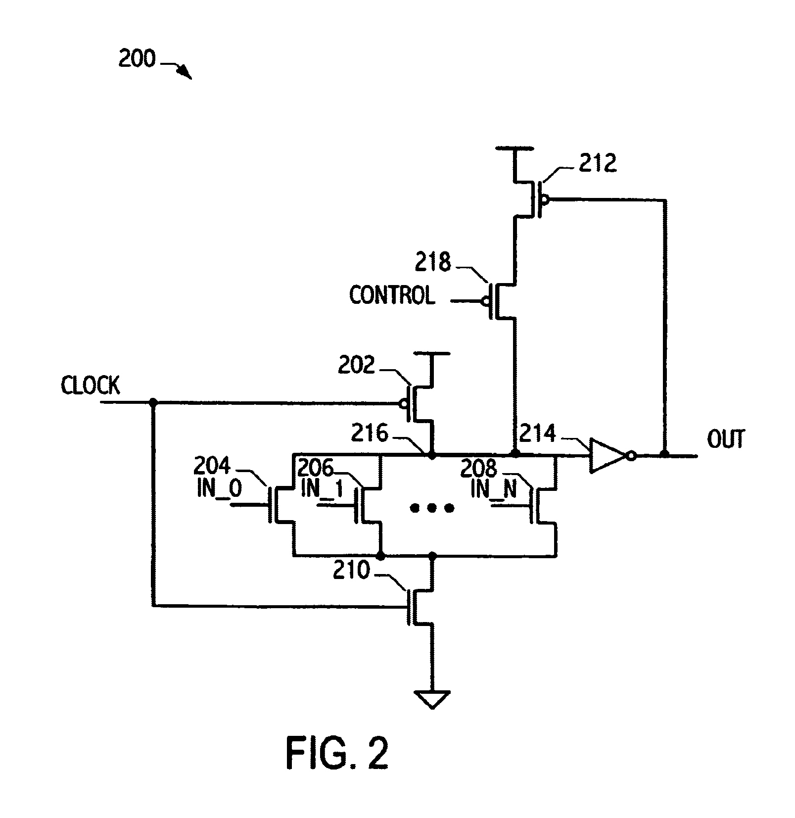
[0021]Referring to FIG. 2, circuit 200 includes keeper 212 in series with keeper gating device 218. Keeper 212 is a p-transistor designed to have a gain sufficient to offset the effects of leakage currents in evaluation circuits with a large number of pull-down devices. The size of keeper 212 may be determined by simulating circuit 200 and determining the W / L ratio of keeper 212 necessary to achieve the appropriate gain, or by any other method for sizing circuit devices known in the art. The additional capacitance of keeper 212 may slow down circuit transitions due to additional capacitance introduced by keeper 212. Pull-down devices 204–210 may be unable to overcome keeper 212 during a time interval in which the inputs are expected to switch. To alleviate these detrimental effects on performance, keeper gating device 218 effectively disables keeper 212 during the time interval when the inputs are expected to switch. In most functional cases, inputs IN_0, IN_1, . . . IN_N switch du...


PUM


Abstract

A circuit has been developed that reduces the effective strength of a keeper circuit during an interval in which at least one path of an evaluation circuit is sensitive to a keeper device. The keeper circuit includes a keeper gating device coupled to a keeper device that is responsive to a keeper control. The keeper device is sized to overcome leakage current in the evaluation circuit. In some configurations, the keeper circuit includes a weak keeper device that is minimally sized to overcome noise while the keeper device is effectively disabled. In some configurations, the reduction in effective strength of the keeper circuit occurs before arrival of the fastest signal coupled to a sensitive output path of the evaluation circuit and the effective strength is restored after arrival of the slowest signal coupled to the sensitive output path of the evaluation circuit.

Description

CROSS-REFERENCE TO RELATED APPLICATION(S)[0001]This application claims the benefit under 35 U.S.C. § 119(e) of U.S. Provisional Application No. 60 / 479,691, filed Jun. 19, 2003.BACKGROUND[0002]1. Field of the Invention[0003]This invention relates to dynamic circuits and more particularly to keeper devices utilized in dynamic circuits.[0004]2. Description of the Related Art[0005]Dynamic Complementary Metal Oxide Semiconductor (CMOS) circuits precharge a node and conditionally discharge the node based on inputs evaluated by the circuit. Referring to FIG. 1, a prior art OR circuit 100 is illustrated with a p-channel precharge device 102 and n-channel evaluation logic. The n-channel evaluation logic includes devices 104–108 and an n-channel ground switch 110. Devices 102 and 110 are enabled during opposite phases of the signal CLOCK, disabling at least one transistor in the path between VDD and VSS at a given time. Therefore, a DC current path does not exist from VDD to VSS and the stead...

Claims


Application Information

Patent Timeline
Patent Type & Authority Patents(United States)
IPC IPC(8): H03K19/096
CPCH03K19/0963
Inventor LEVY, HOWARDELEYAN, NADEEMSHARMA, HARSHKIM, HONG
Owner ORACLE INT CORP
Why Eureka
Try Eureka