Non-contact auxiliary switch and electric power apparatus incorporating same

a technology of non-contact auxiliary switches and electric power apparatuses, applied in circuit-breaking switches, relays, pulse techniques, etc., can solve the problems of physical insufficient space or physical insufficient space of electric power apparatuses

Inactive Publication Date: 2006-04-25
EATON CORP
View PDF6 Cites 9 Cited by
  • Summary
  • Abstract
  • Description
  • Claims
  • Application Information

AI Technical Summary

Benefits of technology

[0007]The magnetically responsive sensor can be a Hall effect device, in which a magnetic field of sufficient strength perpendicular to current flow through the device, switches its effective impedance.
[0008]The auxiliary switch of the invention includes, in addition to the magnetic sensor, a magnet and a moving piece attached to or part of the operating mechanism of the apparatus and which moves with the contacts between open and closed positions. The magnet can be carried by the moving piece, or alternatively, the moving piece can be magnetized to form the magnet. In these embodiments of the invention, the magnetic field is perpendicular to current flow through the Hall effect device in one position of the movable piece and sufficiently non-perpendicular in a second position to cause switching of the sensor.
[0009]In another embodiment of the invention, the moving piece is mounted between the magnet and the sensor, and either attenuates or does not attenuate the magnetic field reaching the Hall effect device.
[0010]More particularly, the invention is directed to a non-contact auxiliary switch for an electric power apparatus comprising a housing containing separable contacts and an operating mechanism operating the separable contacts between open and closed positions. The auxiliary switch comprises a magnet generating a magnetic field, a Hall effect device responsive to first and second conditions of the magnetic field to generate first and second outputs signals, and a moving piece coupled to and moved by the operating mechanism between a closed position when the contacts are closed to effect one of the first and second conditions of the magnetic field, and an open position when the contacts are open to effect the other of the first and second conditions of the magnetic field.

Problems solved by technology

Some electric power apparatuses are physically too small or otherwise do not have sufficient space available for the auxiliary switch within the housing.
However, this requires an opening in the housing for the mechanical linkage.

Method used


Image

  • Non-contact auxiliary switch and electric power apparatus incorporating same
  • Non-contact auxiliary switch and electric power apparatus incorporating same
  • Non-contact auxiliary switch and electric power apparatus incorporating same

Examples


Embodiment Construction

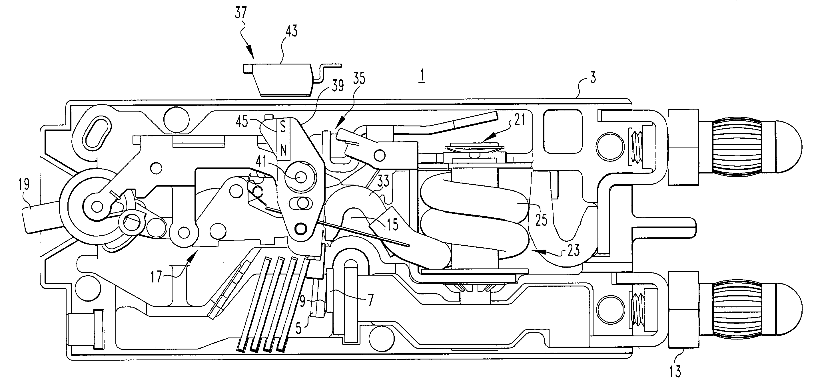
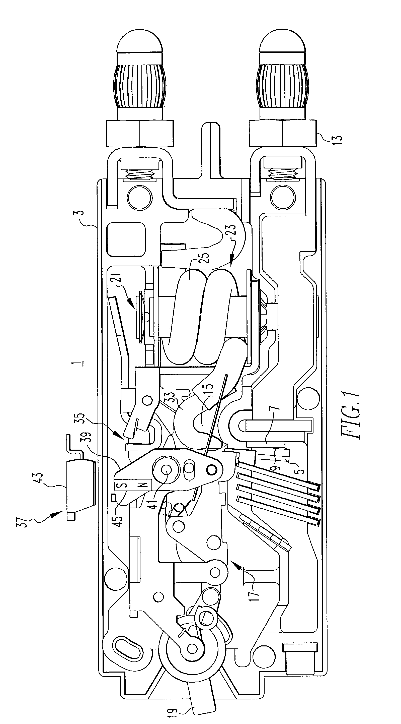
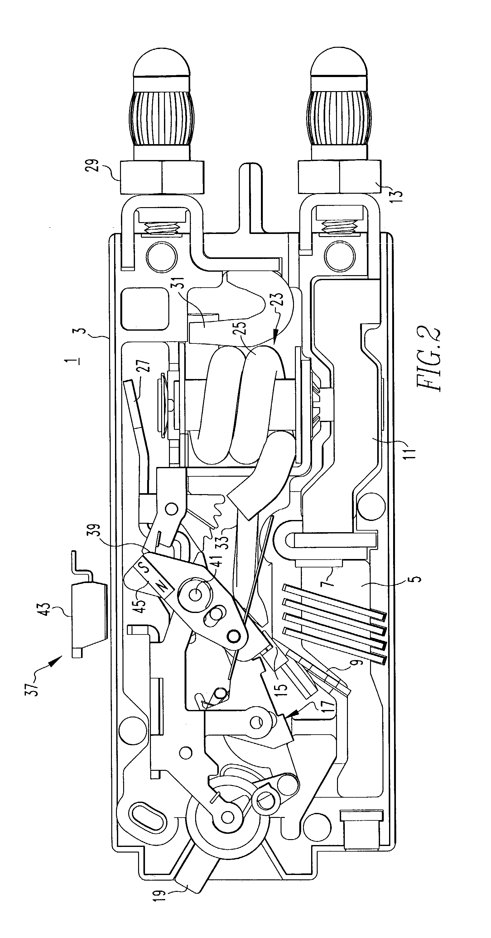
[0016]The invention will be described as applied to a circuit breaker, but it will be apparent that it has application to other electric power switching apparatus. Referring to FIG. 1, the circuit breaker 1 has a molded housing 3. Within the housing is a set of separable contacts 5 formed by a fixed contact 7 and a movable contact 9. The fixed contact 7 is mounted on a load conductor 11 which extends outside of the housing 3 where it terminates in a load terminal 13. The movable contact 9 is mounted on a movable contact arm 15, which forms part of an operating mechanism 17. The operating mechanism 17 includes a handle 19 which can be used to manually move the movable contact arm 15 between a closed position shown in FIG. 1 in which the separable contacts 5 are closed and an open position shown in FIG. 2 in which the separable contacts are open.

[0017]The operating mechanism 17 can also be actuated automatically by a trip mechanism 21. In the exemplary circuit breaker 1, this trip mec...


PUM


Abstract

The auxiliary switch includes a non-contact sensor, such as a Hall effect device, that is switched by the condition of a magnetic field. The magnetic field condition is effected by a movable contact indicator that moves between open and closed positions with the separable contacts of the electric power apparatus. A magnet may be attached to the movable contact indicator, or the movable contact indicator can be magnetized to form the magnet. Alternatively, the moving contact indicator can intercept or not intercept a magnetic field produced by a fixed magnet spaced from the sensor. The Hall effect device may be mounted on the outside of the nonmagnetically permeable housing of the electric power apparatus, or inside if there is sufficient room. In either case, no mechanical coupling is required for the sensor.

Description

BACKGROUND OF THE INVENTION[0001]1. Field of the Invention[0002]This invention relates to a switch that signals a specified condition of the electric power apparatus, and more particularly to a non-contact switch that includes a sensor requiring no mechanical actuation by the apparatus, and to an electric power apparatus incorporating such a switch.[0003]2. Background Information[0004]Electric power apparatus, such as circuit breakers, transfer switches, network protectors, and the like, often are equipped with auxiliary switches that provide signals indicating certain conditions within the apparatus. These include switches that indicate whether the contacts are open or closed and whether the device has been tripped open. The signals generated by the switches can be used for communicating the condition to a remote location.[0005]Typically, these auxiliary switches are mechanically actuated, usually through physical contact with or a linkage to the operating mechanism that opens and ...

Claims


Application Information

Patent Timeline
Patent Type & Authority Patents(United States)
IPC IPC(8): H01H9/00H01H36/00H01H71/04H03K17/97
CPCH03K17/97H01H71/04H01H36/00H01H36/008H01H2071/048
Inventor MOLDOVAN, PETER K.WELLNER, EDWARD L.LARSEN, MICHAEL R.ROLLMANN, PAUL J.ZHOU, XINSKIBINSKI, JOHN R.GAZDECKI, RANDAL D.
Owner EATON CORP
Why Eureka
Try Eureka