A/D converter apparatus and D/A converter apparatus including a digital filter

a converter apparatus and converter technology, applied in the direction of code conversion, recording signal processing, instruments, etc., can solve the problems of remarkable deterioration of characteristics, and achieve the effects of preventing the increase of circuit scale, reducing the order of digital filters, and reducing circuit scal

Inactive Publication Date: 2006-04-25
PANASONIC CORP
View PDF6 Cites 17 Cited by
  • Summary
  • Abstract
  • Description
  • Claims
  • Application Information

AI Technical Summary

Benefits of technology

[0020]An object of the present invention is to provide an A / D converter apparatus and a D / A converter apparatus which can realize sharp characteristics in a transition band, while preventing a circuit scale from being increased in a high pass filter design.
[0024]If the change of the gradient due to the above-mentioned sampling rate is used, a desired gradient can be obtained by adjusting the sampling rate in the state that the high pass filter is designed so that the gradient thereof is smoother than the gradient of the needed transition band. Also, by introducing this method, the increment of the circuit scale can be prevented without increasing the order of the filter.
[0027]According to the present invention, although the sharp change in the transition band is required with respect to the frequency characteristics of the high pass filter, only by decreasing the sampling rate of the input signal, the sharp change can be accomplished without increasing the order of the digital filter and the circuit scale can be prevented from be increased. Also, although there is no a change in the required frequency characteristics, the order of the digital filter can be decreased by decreasing the sampling rate and the circuit scale can be reduced.

Problems solved by technology

However, since the digital signal obtained by performing A / D conversion often includes quantization noise generated from the quantization process and aliasing noise generated from sampling process, a process for removing these noises is typically required.
However, if only down-sampling is simply performed, the aliasing noise and the quantizing noise may be mixed to the needed signal band to remarkably deteriorate the characteristics thereof.

Method used


Image

  • A/D converter apparatus and D/A converter apparatus including a digital filter
  • A/D converter apparatus and D/A converter apparatus including a digital filter
  • A/D converter apparatus and D/A converter apparatus including a digital filter

Examples


first embodiment

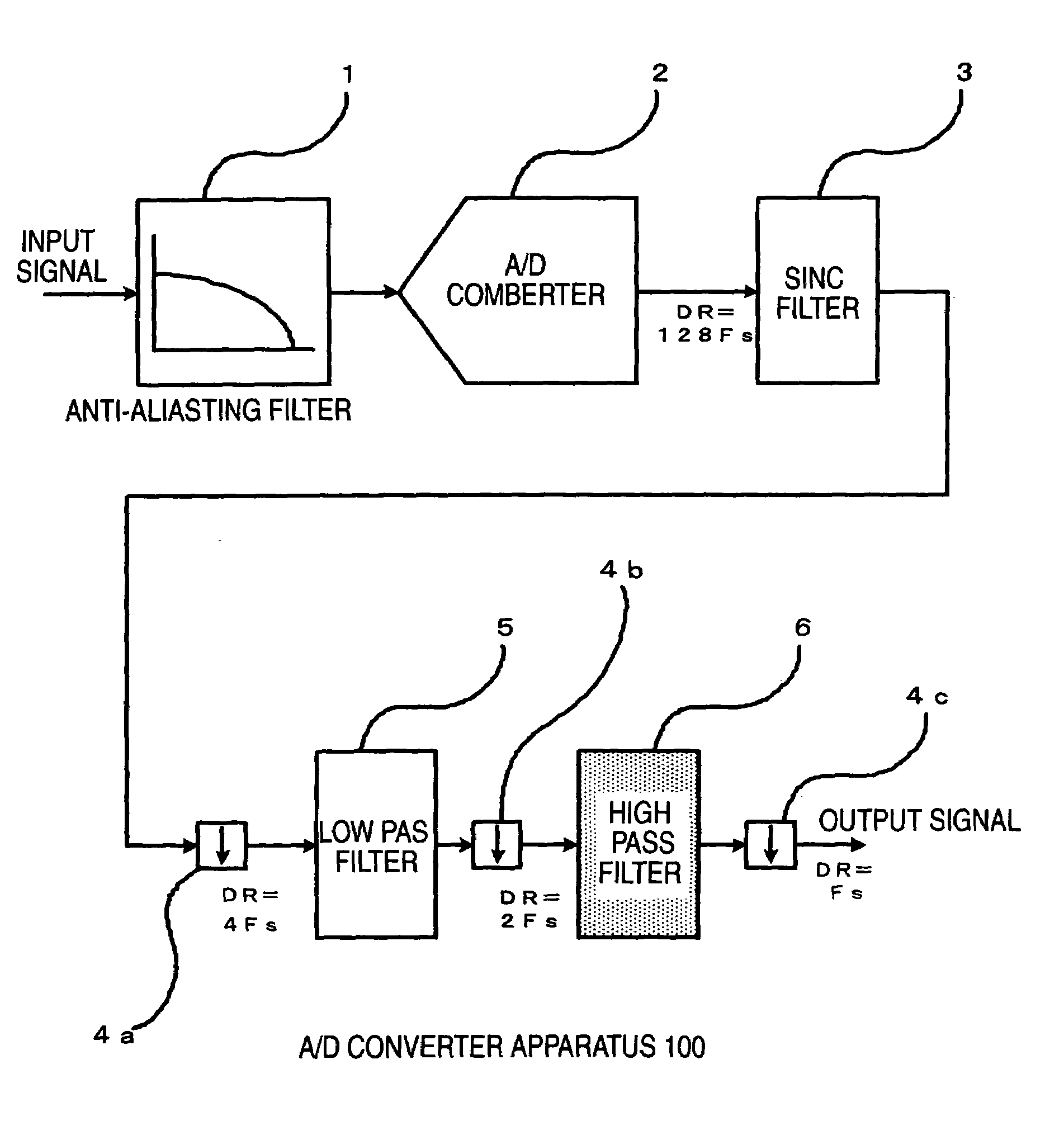
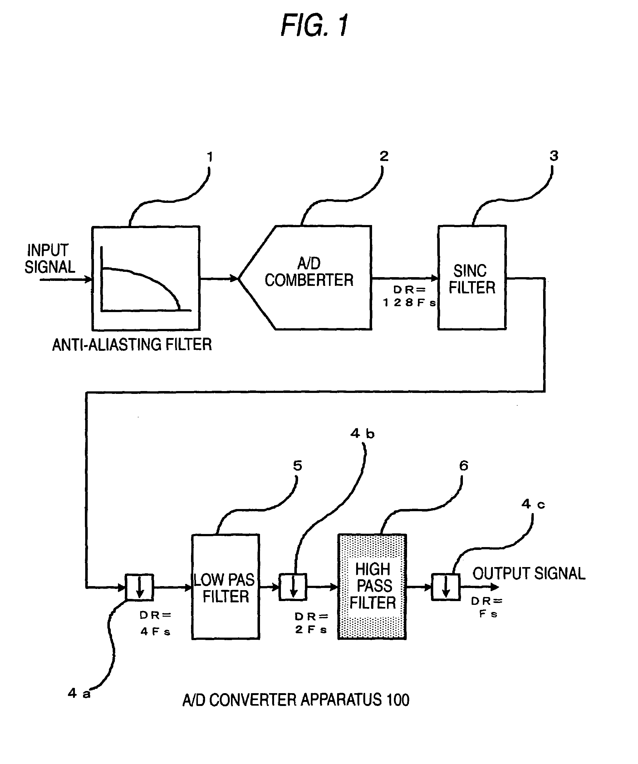
[0033]FIG. 1 is a block diagram showing a schematic structure of an A / D converter apparatus 100 according to a first embodiment of the present invention. The A / D converter apparatus 100 comprises an anti-aliasing filter 1 for previously removing an aliasing noise generated by sampling, an A / D converter 2 for converting an analog signal into a digital signal at a sampling rate of 128Fs (Fs is the data rate of the digital signal which is desired to be obtained), a SINC filter (comb filter) 3 for removing an aliasing noise due to down-sampling, a first decimator 4a for performing down-sampling at the data rate of DR=4Fs, a low pass filter 5 for removing an aliasing noise due to down-sampling, a second decimator 4b for performing down-sampling at the data rate of DR=2Fs, a high pass filter 6 for removing a DC component from a signal output from the decimator 4b, and a third decimator 4c for down-sampling a signal output from the high pass filter 6 at the data rate of DR=Fs.

[0034]The ant...

second embodiment

[0047]FIG. 3 is a block diagram showing a schematic structure of a D / A converter apparatus 200 of a second embodiment of the present invention. The D / A converter apparatus 200 comprises a first interpolator 7a for increasing the data rate of a digital input signal to 2Fs, a high pass filter 6 for removing a DC component, similar to the first embodiment, a second interpolator 7b for increasing the data rate thereof to 4Fs, a first low pass filter 5 for removing the spectrum at 2Fs, 3Fs among the spectrums of the digital input signal which are repeated at the interval of Fs and allowing the spectrum to be repeated for each 4Fs, a third interpolator 7c for increasing the data rate to 128Fs, a second low pass filter 8 for removing the spectrum which exists at the interval of 4Fs, a D / A converter 9 for converting the digital signal into an analog signal, and a smoothing filter 10 for removing an aliasing spectrum shifted to the band of 128Fs by the third interpolator 7c and extracting on...

third embodiment

[0049]FIG. 4 is a block diagram showing a schematic structure of an A / D and D / A converter apparatus 300 composed by combining the A / D converter apparatus 100 described in the first embodiment and the D / A converter apparatus 200 described in the second embodiment. The A / D and D / A converter apparatus 300 of the present embodiment comprises an anti-aliasing filter 1, an A / D converter 2, a SINC filter (comb filter) 3, first to third decimators 4a, 4b, and 4c, a first low pass filter 5, a high pass filter 6, first to third interpolators 7a, 7b, and 7c, a second low pass filter 8, a D / A converter 9, a smoothing filter 10, and first to third switches 11a, 11b, and 11c each having a terminal A and a terminal B which are switched in response to a control signal as a sharing means for switching data paths for A / D conversion and D / A conversion.

[0050]The functions of the components are equal to that described in the first and second embodiments. The A / D and D / A converter apparatus 300 functions...


PUM

PropertyMeasurementUnit
frequencyaaaaaaaaaa
speedaaaaaaaaaa
spectrumaaaaaaaaaa

Abstract

An A / D converter apparatus for converting an analog signal output from an anti-aliasing filter into a digital signal, a sinc filter for removing a frequency component corresponding to an aliasing noise generated by down-sampling, a first decimator for down-sampling a signal output from the sinc filter, a low pass filter for removing a frequency component corresponding to an aliasing noise generated by down-sampling, a second decimator for down-sampling a signal output from the low pass filter, and a high pass filter for removing a dc component from a signal output from the second decimator are disclosed.

Description

[0001]This application is based on Japanese Patent Application No. 2003-411412, which is incorporated herein by reference.BACKGROUND OF THE INVENTION[0002]1. Field of the Invention[0003]The present invention relates to an A / D converter apparatus and a D / A converter apparatus comprising a digital filter.[0004]2. Description of the Related Art[0005]An A / D and D / A conversion technique is necessary for connecting information society which demands high-speed and high reliability in digitizing information with the natural world in which all the information is expressed by analog signal, and is widely used in various fields such as audio processing, video processing, and analog signal control.[0006]The A / D conversion means a process for sampling analog signals in a discrete time and quantizing amplitude information to convert it into digital signals. However, since the digital signal obtained by performing A / D conversion often includes quantization noise generated from the quantization pro...

Claims


Application Information

Patent Timeline
Patent Type & Authority Patents(United States)
IPC IPC(8): H03M3/00H03M1/08G11B20/10H03H17/02H03H17/06
CPCG11B20/10527H03H17/0223H03H17/0286H03H17/0664H03H17/0621H03H17/0657H03H17/0294
Inventor URAMOTO, YASUTAKAKANAMORI, KOUJI
Owner PANASONIC CORP
Why Eureka
Try Eureka