Optical disc and optical disc address reading apparatus and method
an optical disc and address reading technology, applied in the direction of digital signal error detection/correction, instruments, recording signal processing, etc., can solve the problem of inability to precisely determine the position where recording starts, and achieve the effect of reducing track pitch, providing address information more efficiently, and crosstalk
- Summary
- Abstract
- Description
- Claims
- Application Information
AI Technical Summary
Benefits of technology
Problems solved by technology
Method used
Image
Examples
embodiment 1
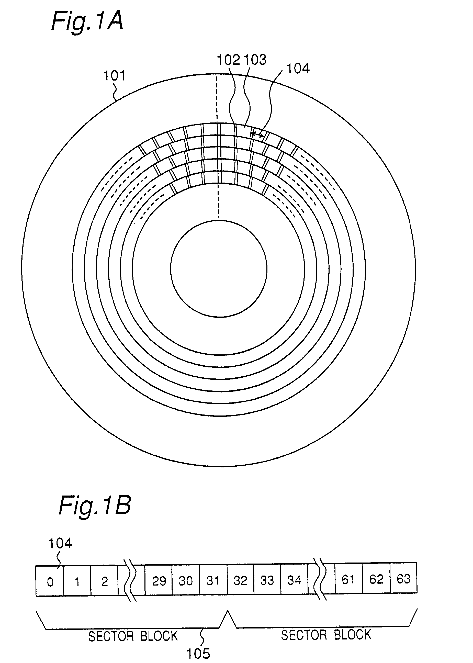
[0179]FIG. 1A is a plan view of an optical disc according to a preferred embodiment of the present invention, and FIG. 1B describes the placement of sector blocks. Shown in FIG. 1A are the optical disc substrate 101, header 102 that is preformed when the disc is made, recording area 103 where data can be recorded, and sector 104, which is the data recording unit. FIG. 1B shows a sector block 105 containing a specific number (such as 32) of sectors.
[0180]A phase change film is formed on the optical disc substrate 101. Data is recorded to this phase change film by optically changing this phase change film between amorphous and crystalline phases, and signals are read using the difference in reflectivity between amorphous and crystal phase parts.
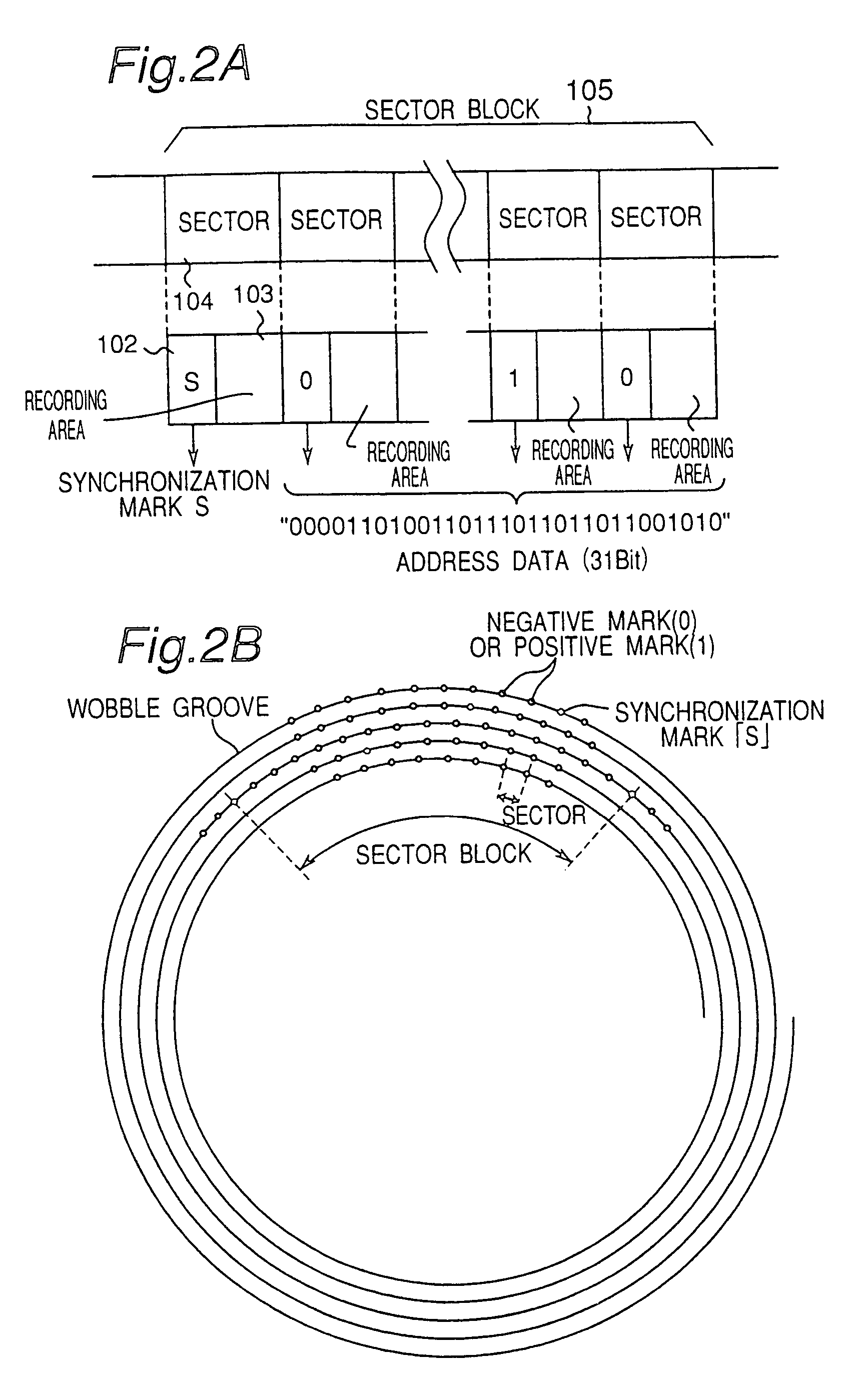
[0181]The relationship between sectors 104 and sector block 105 is described in detail next with reference to FIG. 2A.
[0182]In an optical disc according to this embodiment of the invention a track comprises a number of consecutive sector blocks...
embodiment 2
[0224]In an optical disc according to this second embodiment of the invention dispersed addresses are recorded using groove modifications, more specifically using a groove bottom offset 65, a groove top offset 66, and a combination 67 of groove bottom offset 65 and groove top offset 66 as shown in FIG. 10. In the example shown in FIG. 10 a single groove top offset 66 denotes a positive mark (1); a combination 67 containing a groove bottom offset 65 and a groove top offset 66 appearing within a specified time of the groove bottom offset 65 denotes a synchronization mark S; and a groove bottom offset 65 not followed by a groove top offset 66 within a specific time denotes a negative mark (0). The groove bottom offsets and groove top offsets are generically referred to herein as simply “groove offsets.” Any one of these parts 65, 66, 67 can be used as a synchronization mark, positive mark, or negative mark, but combination 67 is preferably used as the synchronization marks, which are d...
first alternative embodiment
(First Alternative Embodiment)
[0244]A first alternative version of the groove modifications in the second embodiment of the invention is described below with reference to FIG. 15 to FIG. 20.
[0245]While groove bottom offset 65 and groove top offset 66 are used in the embodiment shown in FIG. 10, these are changed to groove descending-phase inversion part 74 and groove ascending-phase inversion part 75 in this first alternative embodiment as shown in FIG. 17. The groove descending-phase inversion part 74 vertically inverts the phase of the sinusoidal wobble wave from the groove peak to the groove trough, that is, an approximately ¼ phase segment of the wobble period from the groove peak. The groove ascending-phase inversion part 75 similarly vertically inverts the phase of the sinusoidal wobble wave from the groove trough to the groove peak, that is, an approximately ¼ phase segment of the wobble period from the groove trough. The groove descending-phase inversion and groove ascending...
PUM
| Property | Measurement | Unit |
|---|---|---|
| magneto-optical | aaaaa | aaaaa |
| recording density | aaaaa | aaaaa |
| constant linear velocity | aaaaa | aaaaa |
Abstract
Description
Claims
Application Information
 - R&D
- Intellectual Property
- Life Sciences
- Materials
- Tech Scout
- Unparalleled Data Quality
- Higher Quality Content
- 60% Fewer Hallucinations
Browse by: Latest US Patents, China's latest patents, Technical Efficacy Thesaurus, Application Domain, Technology Topic, Popular Technical Reports.
© 2025 PatSnap. All rights reserved.Legal|Privacy policy|Modern Slavery Act Transparency Statement|Sitemap|About US| Contact US: help@patsnap.com


